Northernboy
Pro
I am getting ready to put a head shim into a Nytro and would like to know if there are any good instruction and/or tips on how to get the head torque done properly and the valve timing done?
Thanks
Thanks
dirk_03
Expert
Here is my write up from doing a vector motor. The vector and nytro motors are very similar. You can do it this way or call powderlites and try to buy the jig from them. Really though the following way is not hard.
I figured since I just did it I would do a write up on it. If there is something i miss or need correction on please feel free to point it out.
I am going to start assuming that you have the valve cover off. Also please reference the service manual for cam removal and torque specs and sequeances. If you dont have one you can find them on ebay or online for $5 for the cd of the service manual. It is very worth having.
Pic of the tools needed.
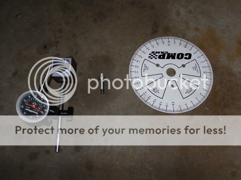
1. Mount the degree wheel on the clutch(vector and nytro).
2. Fab a pointer off a rigid point on the motor. That goes to the degree wheel.
3. Set the motor at TDC on the cylinder closest to the cam chain. Do this by lining up the timing mark on the flywheel and the mag cover.
4. Set the degree wheel to 0 degrees TDC.
5. Loosen the cam chain tensioner with small straight screwdriver. I removed it from the engine.
6. !!!!!VERY IMPORTANT!!!!! Do NOT turn the engine over after this step until the the tensioner has been reinstalled.
7. You can either remove the cams now and remove the gears to slot them or you can just remove the gears and slot them. ****be careful to not drop the bolts into the crankcase.
8. Keep good track of which gears go to the intake and exhaust as you do not want to get this screwed up. It would be best to mark them with a tag or a sharpie.
9. When looking at the gears, slot from the side with the stamped writing. Slot the Holes on the exhaust cam clockwise about half way to the next hole in the gear. Slot the intake gear counterclockwise aprox half way to the next gear. Use care when doing this.
10. Reinstall gears. Reinstall cams if you removed them.
11. follow service manual for reinstalling cam chain, tensioner, etc.
12. Now you should be able to turn the engine over again. Do so with care, and very slowly for the first couple rotations. Do not force it past any resesitance. Also watch to see that the timing chain has not jumped a tooth.
13. Install tdc stop in the end spark plug hole. I used a bolt i got at the hardware store that matched the spark plug threads I think it was a m10x1.00 and was 50mm long.
14. Now turn the motor over slowly backwards until the piston stops on the stop. Now note the reading of the pointer on the degree wheel. Write it down. Then turn the motor over the corect direction slowly till it stops at the stop again. Note the reading on the degree wheel. A good example would be the first measurement was 104 degrees and the second was 140 degrees. You need to split the number. Mine was closer than that from setting the degree wheel at tdc earlier. Either way what you want to do is split the number. You would get 18 degrees.
15. Loosen and rotate the degree wheel(not the motor) to 0 TDC and then remove the piston stop. Now rotate the motor to 18 degrees. Stop loosen the degree wheel again using care to not rotate the motor and set the degree wheel to 0 TDC once again.
16.Now setup a mag base and dial indicator like shown below. On the intake cam.
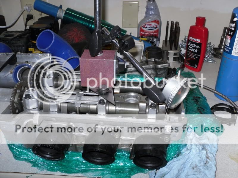
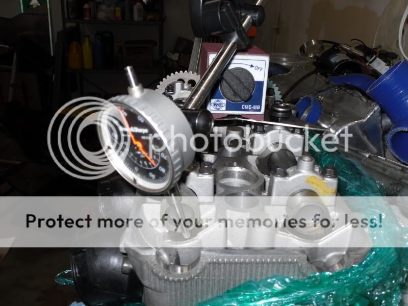

17. Set the dial indicator to 0.
NOTE:do not rotate the engine backwards if you go past just rotate forward. this needs to be done to keep the timing chain tension correct int he next steps.
18. Now rotate the engine until the dial indicator reads .040 of valve lift. Write down the reading from the degree wheel. An example would be that i had 5 degrees.
19. Now continue rotating the crank until the dial indicator indicates .040 before closing. EXample I got 46 degrees
20. Now for the math.
Intake cam
OPEN 5 degrees
close 46 degress
add =51
add 180
= 231/2
=115.5
- 5
= 110.5
This gives me 110.5 lobe centers.
Now repeat the exhaust side. Always subract the smaller of the opening and closing numbers as seen above.
After having the cams where i wanted them I removed the degree wheel and reinstalled everything again and checked my work once again, I did this 3 times to be sure of my work. It was the same every time. Then I was confident I had done it correct. It was good for peace of mind.
Again, I am no expert I am just trying to help those out there trying to do this themselves. Really it was not that bad to do.
It is also best to set your cams to what your turbo manufacture reccommends. I set mine at 110.5 and 113.5. AS powderlites told me that anything over 110 is really good on the vector motor.
I figured since I just did it I would do a write up on it. If there is something i miss or need correction on please feel free to point it out.
I am going to start assuming that you have the valve cover off. Also please reference the service manual for cam removal and torque specs and sequeances. If you dont have one you can find them on ebay or online for $5 for the cd of the service manual. It is very worth having.
Pic of the tools needed.
1. Mount the degree wheel on the clutch(vector and nytro).
2. Fab a pointer off a rigid point on the motor. That goes to the degree wheel.
3. Set the motor at TDC on the cylinder closest to the cam chain. Do this by lining up the timing mark on the flywheel and the mag cover.
4. Set the degree wheel to 0 degrees TDC.
5. Loosen the cam chain tensioner with small straight screwdriver. I removed it from the engine.
6. !!!!!VERY IMPORTANT!!!!! Do NOT turn the engine over after this step until the the tensioner has been reinstalled.
7. You can either remove the cams now and remove the gears to slot them or you can just remove the gears and slot them. ****be careful to not drop the bolts into the crankcase.
8. Keep good track of which gears go to the intake and exhaust as you do not want to get this screwed up. It would be best to mark them with a tag or a sharpie.
9. When looking at the gears, slot from the side with the stamped writing. Slot the Holes on the exhaust cam clockwise about half way to the next hole in the gear. Slot the intake gear counterclockwise aprox half way to the next gear. Use care when doing this.
10. Reinstall gears. Reinstall cams if you removed them.
11. follow service manual for reinstalling cam chain, tensioner, etc.
12. Now you should be able to turn the engine over again. Do so with care, and very slowly for the first couple rotations. Do not force it past any resesitance. Also watch to see that the timing chain has not jumped a tooth.
13. Install tdc stop in the end spark plug hole. I used a bolt i got at the hardware store that matched the spark plug threads I think it was a m10x1.00 and was 50mm long.
14. Now turn the motor over slowly backwards until the piston stops on the stop. Now note the reading of the pointer on the degree wheel. Write it down. Then turn the motor over the corect direction slowly till it stops at the stop again. Note the reading on the degree wheel. A good example would be the first measurement was 104 degrees and the second was 140 degrees. You need to split the number. Mine was closer than that from setting the degree wheel at tdc earlier. Either way what you want to do is split the number. You would get 18 degrees.
15. Loosen and rotate the degree wheel(not the motor) to 0 TDC and then remove the piston stop. Now rotate the motor to 18 degrees. Stop loosen the degree wheel again using care to not rotate the motor and set the degree wheel to 0 TDC once again.
16.Now setup a mag base and dial indicator like shown below. On the intake cam.
17. Set the dial indicator to 0.
NOTE:do not rotate the engine backwards if you go past just rotate forward. this needs to be done to keep the timing chain tension correct int he next steps.
18. Now rotate the engine until the dial indicator reads .040 of valve lift. Write down the reading from the degree wheel. An example would be that i had 5 degrees.
19. Now continue rotating the crank until the dial indicator indicates .040 before closing. EXample I got 46 degrees
20. Now for the math.
Intake cam
OPEN 5 degrees
close 46 degress
add =51
add 180
= 231/2
=115.5
- 5
= 110.5
This gives me 110.5 lobe centers.
Now repeat the exhaust side. Always subract the smaller of the opening and closing numbers as seen above.
After having the cams where i wanted them I removed the degree wheel and reinstalled everything again and checked my work once again, I did this 3 times to be sure of my work. It was the same every time. Then I was confident I had done it correct. It was good for peace of mind.
Again, I am no expert I am just trying to help those out there trying to do this themselves. Really it was not that bad to do.
It is also best to set your cams to what your turbo manufacture reccommends. I set mine at 110.5 and 113.5. AS powderlites told me that anything over 110 is really good on the vector motor.
dirk_03
Expert
Here is my write up from doing a vector motor. The vector and nytro motors are very similar. You can do it this way or call powderlites and try to buy the jig from them. Really though the following way is not hard.
I figured since I just did it I would do a write up on it. If there is something i miss or need correction on please feel free to point it out.
I am going to start assuming that you have the valve cover off. Also please reference the service manual for cam removal and torque specs and sequeances. If you dont have one you can find them on ebay or online for $5 for the cd of the service manual. It is very worth having.
Pic of the tools needed.
1. Mount the degree wheel on the clutch(vector and nytro).
2. Fab a pointer off a rigid point on the motor. That goes to the degree wheel.
3. Set the motor at TDC on the cylinder closest to the cam chain. Do this by lining up the timing mark on the flywheel and the mag cover.
4. Set the degree wheel to 0 degrees TDC.
5. Loosen the cam chain tensioner with small straight screwdriver. I removed it from the engine.
6. !!!!!VERY IMPORTANT!!!!! Do NOT turn the engine over after this step until the the tensioner has been reinstalled.
7. You can either remove the cams now and remove the gears to slot them or you can just remove the gears and slot them. ****be careful to not drop the bolts into the crankcase.
8. Keep good track of which gears go to the intake and exhaust as you do not want to get this screwed up. It would be best to mark them with a tag or a sharpie.
9. When looking at the gears, slot from the side with the stamped writing. Slot the Holes on the exhaust cam clockwise about half way to the next hole in the gear. Slot the intake gear counterclockwise aprox half way to the next gear. Use care when doing this.
10. Reinstall gears. Reinstall cams if you removed them.
11. follow service manual for reinstalling cam chain, tensioner, etc.
12. Now you should be able to turn the engine over again. Do so with care, and very slowly for the first couple rotations. Do not force it past any resesitance. Also watch to see that the timing chain has not jumped a tooth.
13. Install tdc stop in the end spark plug hole. I used a bolt i got at the hardware store that matched the spark plug threads I think it was a m10x1.00 and was 50mm long.
14. Now turn the motor over slowly backwards until the piston stops on the stop. Now note the reading of the pointer on the degree wheel. Write it down. Then turn the motor over the corect direction slowly till it stops at the stop again. Note the reading on the degree wheel. A good example would be the first measurement was 104 degrees and the second was 140 degrees. You need to split the number. Mine was closer than that from setting the degree wheel at tdc earlier. Either way what you want to do is split the number. You would get 18 degrees.
15. Loosen and rotate the degree wheel(not the motor) to 0 TDC and then remove the piston stop. Now rotate the motor to 18 degrees. Stop loosen the degree wheel again using care to not rotate the motor and set the degree wheel to 0 TDC once again.
16.Now setup a mag base and dial indicator like shown below. On the intake cam.
17. Set the dial indicator to 0.
NOTE:do not rotate the engine backwards if you go past just rotate forward. this needs to be done to keep the timing chain tension correct int he next steps.
18. Now rotate the engine until the dial indicator reads .040 of valve lift. Write down the reading from the degree wheel. An example would be that i had 5 degrees.
19. Now continue rotating the crank until the dial indicator indicates .040 before closing. EXample I got 46 degrees
20. Now for the math.
Intake cam
OPEN 5 degrees
close 46 degress
add =51
add 180
= 231/2
=115.5
- 5
= 110.5
This gives me 110.5 lobe centers.
Now repeat the exhaust side. Always subract the smaller of the opening and closing numbers as seen above.
After having the cams where i wanted them I removed the degree wheel and reinstalled everything again and checked my work once again, I did this 3 times to be sure of my work. It was the same every time. Then I was confident I had done it correct. It was good for peace of mind.
Again, I am no expert I am just trying to help those out there trying to do this themselves. Really it was not that bad to do.
It is also best to set your cams to what your turbo manufacture reccommends. I set mine at 110.5 and 113.5. AS powderlites told me that anything over 110 is really good on the vector motor.
Awesome write up Dirk !")


Dirk, thank you for the great write up. Ive made this a Sticky!
rxrider
Jan-Ove Pedersen
- Joined
- Apr 25, 2003
- Messages
- 7,356
- Age
- 59
- Location
- Lakselv - 70N & 25E
- Country
- Norway
- Snowmobile
- 2014 Phazer XTX, 2013 Phazer RTX, 2008 Apex RTX, 2007 Warrior, 2006 Attak
Great work dirk03 - I would like to add a few:
If you add a TDC dial indicator you will be able to set your crank at the TRUE TDC, you will not be able to do that lining up the marks on the flywheel and cover.
Are your opening #s before or after TDC? On the 4 cylinder motors that is important to know cause that determines if your have to add or subtract...
For the RX-1 and Apex I have a double dial indicator fixture, I'm able to measure both cams in one take")
Other than that your writeup is perfect.
Jan-O
rxrider
If you add a TDC dial indicator you will be able to set your crank at the TRUE TDC, you will not be able to do that lining up the marks on the flywheel and cover.
Are your opening #s before or after TDC? On the 4 cylinder motors that is important to know cause that determines if your have to add or subtract...
For the RX-1 and Apex I have a double dial indicator fixture, I'm able to measure both cams in one take
Other than that your writeup is perfect.
Jan-O
rxrider
Similar threads
- Replies
- 5
- Views
- 2K