
- Joined
- Apr 13, 2003
- Messages
- 21,312
- Age
- 54
- Location
- Schofield, WI
- Website
- www.totallyamaha.com
- Country
- USA
- Snowmobile
- 2020 Sidewinder SRX
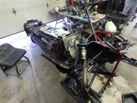
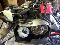
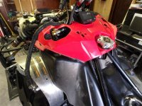
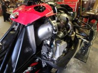
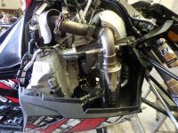
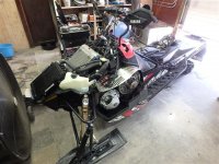
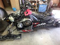
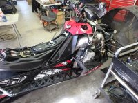
Here is the complete write and info that I put together this spring of 2015 with Allen at Ulmer Racing. What a project it was.


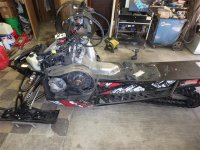
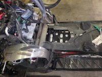
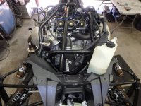
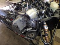
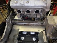

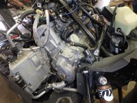
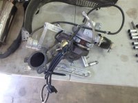
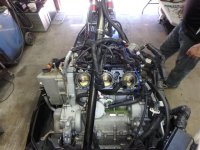
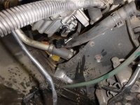
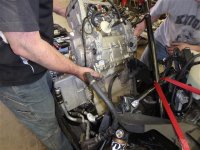
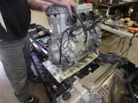
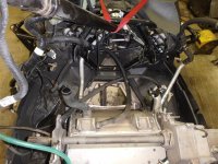
- Remove the side panels, hood, seat and tank cover
- Remove gas tank and battery

- Drain oil and antifreeze - we removed the front bumper for ease of draining the antifreeze. We also removed the right side food well/toe kick to drain the oil
- Remove the inspection pan under the motor as well as the oil filter
- Remove heat shield
- Remove header
- Remove radiator and radiator bracket
- Remove silencer and heat shield
- Remove clutches, belt and clutch guard


- Remove cross member, air filter, and turbo in its entirety (turbo as one package)


- Remove air oil separator
- Remove main structure pipes from steering column down
- Remove throttle cable (put these around the handle bars so they are out of the way) and then throttle bodies
- Pull wiring harness to the left side so it stays out of the way
- Tilt motor forward to remove ground and starter cable
- Disconnect the 2 oil pressure sensors on the bottom of the motor, one is black, one is white
- Pull 2 front motor bolts and pull out motor


Last edited:


- Joined
- Apr 13, 2003
- Messages
- 21,312
- Age
- 54
- Location
- Schofield, WI
- Website
- www.totallyamaha.com
- Country
- USA
- Snowmobile
- 2020 Sidewinder SRX
- Remove spark plug caps
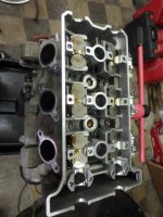
- Remove top motor fasteners and head
- Remove spark plugs
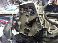
- Line up the OHC with the marks on the cam caps
- Line up the pointer in the fly wheel which dictated top dead center on the #3 cylinder.
- Cams should point to 4:00 and 7:00
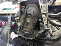
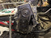
- Line up lines on timing chain gear
- Arrows point to timing chain. "I" indicates intake and "E" indicates exhaust side for cam caps. Intake cam has a single raised area and exhaust has double
- Pay attention to arrow direction on chain tensioner
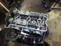
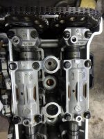
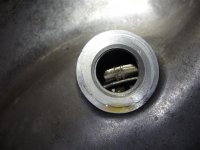
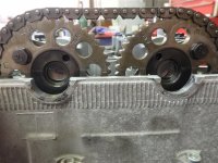
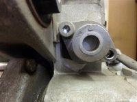
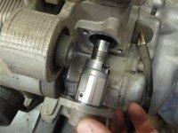
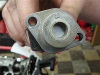
- Do not remove the head bolt with an impact. Always start in the middle and stagger from inside out
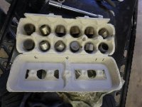
- Use an old egg carton and label it to keep track of the locations
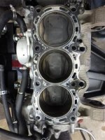
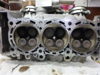
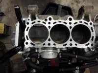
- Remove head and clean both the head and block with carb cleaner and paper towel
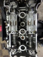
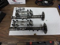


- Joined
- Apr 13, 2003
- Messages
- 21,312
- Age
- 54
- Location
- Schofield, WI
- Website
- www.totallyamaha.com
- Country
- USA
- Snowmobile
- 2020 Sidewinder SRX
- PTO front corner stud cannot be threaded in too far - it will hit the water pump gear
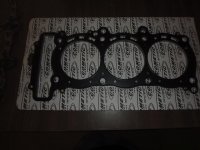
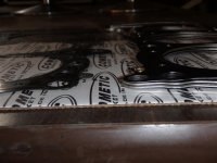
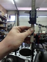
- Install new gasket (. 080"), lube on both sides of washers and back side of nut
- Torque in 3 steps - center out crisscross
- 1st: 15 ft/lbs
- 2nd: 30 ft/lbs
- 3rd: 45 ft/lbs
- Walk away for some time, then come back and loosen each bolt by 1 1/2 turn and re-torque to last setting
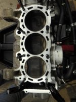
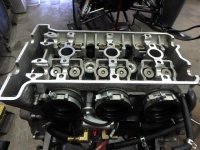
- Remove intake boots and wash in hot soapy water
- Shim cams
- Advance timing one linkage on chain
- Reinstall head with Yamabond
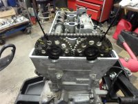
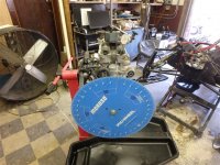
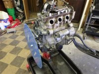
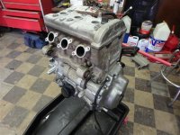
- Reinstall cleaned boots with Yamabond
- Reinstall throttle bodies with Yamabond
- Reinstall motor, opposite of removal steps
- Install oil separator bypass
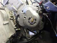
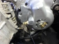
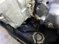
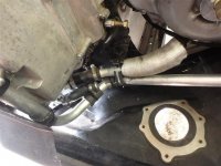
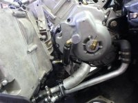


- Joined
- Apr 13, 2003
- Messages
- 21,312
- Age
- 54
- Location
- Schofield, WI
- Website
- www.totallyamaha.com
- Country
- USA
- Snowmobile
- 2020 Sidewinder SRX
- Put silicon on exhaust gasket
- Reinstall turbo, waste gate, air filter, opposite of removal steps
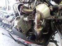
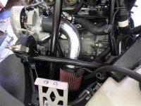
- Reinstall and re-route oil lines, coolant lines for oil separator and thermostat housing
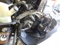
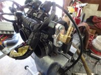
- Install 4th injector kit and updated fuel pump
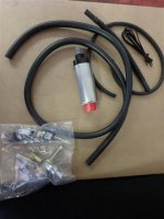
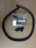
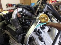
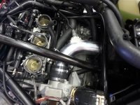
- On throttle bodies, use another screw driver to remove screws, see photo
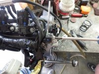
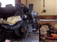
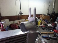
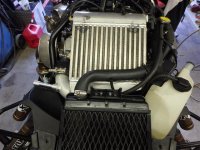
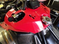
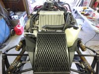
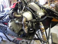
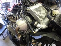
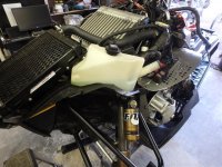
- See photos showing modifications to inter-cooler
- Fuel hose needed was about 5 1/2"


- Joined
- Apr 13, 2003
- Messages
- 21,312
- Age
- 54
- Location
- Schofield, WI
- Website
- www.totallyamaha.com
- Country
- USA
- Snowmobile
- 2020 Sidewinder SRX
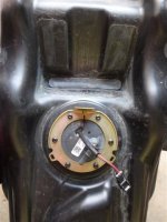
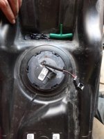
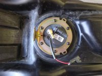
- Mark, as shown in photo, fastening ring that holds fuel pump into tank. Be sure that the mark is on both the ring and fuel pump
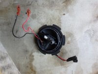
- Unhook power
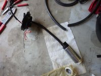
- Remove ring and fuel pump and very carefully pull out lines and filters
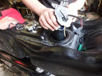
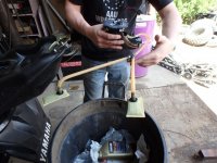
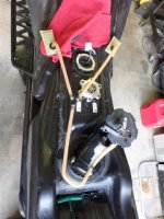
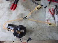
- Turn the white clips on the pump housing from perpendicular to parallel to remove pump covers to expose pump, filters, and hoses
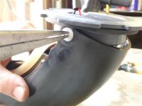
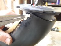
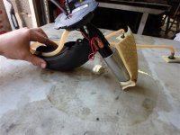
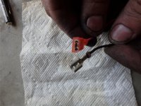
- Remover power, positive and negative, from pump and bottom filter
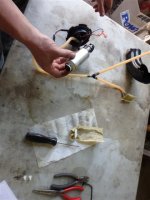
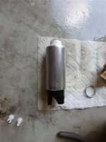
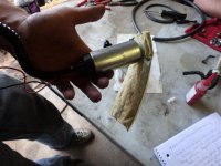
- Remove metal ring from bottom of pump
- Remove corrugated line and pump
- Remove filer Y line


- Joined
- Apr 13, 2003
- Messages
- 21,312
- Age
- 54
- Location
- Schofield, WI
- Website
- www.totallyamaha.com
- Country
- USA
- Snowmobile
- 2020 Sidewinder SRX
- To remove the fuel pressure regulator assembly, push all 4 inner tabs in at the same time (you may need a couple extra hands for this)
- Pry tabs gently to remove white pressure regulator
- Swap o-ring to the new block off
- Put into assembly and reinstall
- Install sealed washer onto the brass 90 degree fitting
- Drill a hole into cap, approx .389"
- Install nut onto backside of brass elbow, use red lock-tite and tighten
- Snap pressure regulator assembly back in
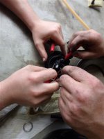
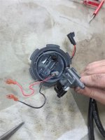
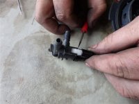
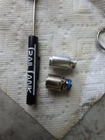
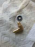
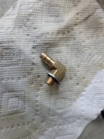
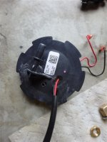
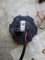
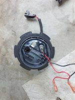
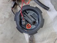
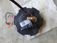
- Put metal ring back into fuel filter
- Remove existing ground prong and install new one provided
- Push corrugated tubes onto cap
- Connect positive and negative
- Connect fuel filter to bottom of pump
- Put assembly back into sleeve and cup
- Reinstall white clips, perpendicular is locked
- Reconnect filter Y hose
- Make sure gasket is on the bottom side of cup
- Fish assembly back into tank and fasten, making sure the mark you made is pointing towards the battery, as shown in previous photos
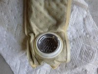


- Joined
- Apr 13, 2003
- Messages
- 21,312
- Age
- 54
- Location
- Schofield, WI
- Website
- www.totallyamaha.com
- Country
- USA
- Snowmobile
- 2020 Sidewinder SRX
- Install throttle bodies with Yamabond
- Reinstall radiator and hoses
- Reinstall tank, hoses, throttle cable, wiring harness. Everything installed in reverse sequence
- Install Power Commander modules and accessories
- Run all remaining wires and fuel lines
- Don't forget to fill antifreeze and oil once everything is put back together!!


- Joined
- Apr 13, 2003
- Messages
- 21,312
- Age
- 54
- Location
- Schofield, WI
- Website
- www.totallyamaha.com
- Country
- USA
- Snowmobile
- 2020 Sidewinder SRX


- Joined
- Apr 13, 2003
- Messages
- 21,312
- Age
- 54
- Location
- Schofield, WI
- Website
- www.totallyamaha.com
- Country
- USA
- Snowmobile
- 2020 Sidewinder SRX
Here are the Vids from some of the final tunes.
Well where are the numbers? I think it would be interesting to look at the hp from the same dyno for 2 of them at 12#'s mine has low comp pistons vs head shim
The blue line is at I believe 9#'s and the red is at 12#'s


- Joined
- Apr 13, 2003
- Messages
- 21,312
- Age
- 54
- Location
- Schofield, WI
- Website
- www.totallyamaha.com
- Country
- USA
- Snowmobile
- 2020 Sidewinder SRX
I will see if Allen can send me that graph over.
bleedyamaha
TY 4 Stroke Master
- Joined
- Sep 28, 2013
- Messages
- 1,490
- Location
- Northern Iowa
- Country
- USA
- Snowmobile
- 2017 Yamaha Sidewinder Rtx Le 2012 Yamaha Vector Ltx
Wow all that looks overwhelming. I was hoping to do my own install If I buy a 190 kit.
oh the 190 kit is no problem its when you go above 6#'s of boost. He is now at about 252 hp


- Joined
- Apr 13, 2003
- Messages
- 21,312
- Age
- 54
- Location
- Schofield, WI
- Website
- www.totallyamaha.com
- Country
- USA
- Snowmobile
- 2020 Sidewinder SRX
oh the 190 kit is no problem its when you go above 6#'s of boost. He is now at about 252 hp
Exactly... 190 is still a job but nothing like this.
Similar threads
- Replies
- 11
- Views
- 3K
- Replies
- 25
- Views
- 46K
-
This site uses cookies to help personalise content, tailor your experience and to keep you logged in if you register.
By continuing to use this site, you are consenting to our use of cookies.

