TurboMatt
Pro
Def. keep us updated. It's nice to have different options. Right now I'm leaning towards the RSI option, but only because I want to keep the stock bars intact. Artex...def. keep us updated. Any idea when you will have it all done? I'm curious to see how they work
ruffryder
TY 4 Stroke Junkie
arteeex said:Has anyone got a handle on the power delivery mode or duty cycle yet?
I will have results Saturday night!!!!

Yes yes yes, about fricken time....
arteeex
TY 4 Stroke Master
We got heat!
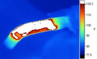
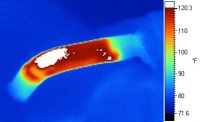
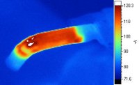
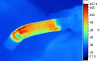
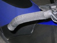
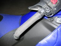
I figured out what I was doing and fired the mothers up. Below are some pictures of the grand experiment and IR images to show the results of this effort. I installed the RSI heater for OVER the stock grips.
I recorded 120F after idling for about 3.5-minutes. With a 15-second rev at 4000+ RPM the grip temp reached 135F. The control was set to high for this run. Ambient temp was about 75F tonight.
Here’s the brief description of what I did.
1) I used a strip of sandpaper to remove the ribs from the surface of the existing grips to provide a smooth surface for the heaters.
2) Determined the best location to install the heater elements; you will see fewer wrinkles in the heater element at the transition to the bar hook when properly positioned.
3) Wrapped cloth filled friction tape around the extreme ends of the heater elements to secure them to the grips – the adhesive on the back of the heaters won’t stick to the grips after they’ve been sanded smooth.
4) I wrapped aluminum flue tape around the heaters on the straight sections of the bars. My theory here is that the conductivity of the aluminum will help reduce hotspots in the heaters – and its adhesive backing is appropriate in this application.
5) Then I wrapped layer of cloth friction tape over the whole deal capture everything.
6) Over the tape I added a layer of fabric heat shrink tubing and capped each end with a wrap of the friction tape.
Before I wired the heaters into the receptacles used for the stock grips, I checked the resistance of each heater element separately and when combined in parallel. Then, by connecting the RSI heater leads to the battery I was able to measure the current of two wiring configurations. The configuration I used for this test measured 1.7-Ohms and drew 6.6A at 12.3V. For comparison, the stock grips drew 3.27A when connected in the same manner. I think I’ll add a couple of ¼ Ohm power resistor to each side before I button everything back up. For my own comfort I would like to see the resistance in the system a bit over 2 Ohms just to knock the current demand to below 6A.
After I load my numbers into Excel I’ll post info on the current and wattage output for the different wiring configurations.
Sorry about the pics being out of order. But I think you'll get the idea. They got HOT!
Attachments
ruffryder
TY 4 Stroke Junkie
arteex,
good job on the resistance measurements... I was assuming that white was ground with the info given to me. I should of caught that since I assumed....
Now that I have them here in front of me, I agree with your schematic, well done I might add.
Upon looking at this though, I am not sure that you need to follow there order... We could still use white as ground and tie the blue and red lines together in parallel as previously discussed.
I am curious if the current would be too much for the handwarmers with both of them going full....
Note that so far it is assumed that at max is 50% duty cycle, so the heat you are seeing in the battery is twice as much as anticipated....
I got the scope in the Jeep and will play with it after I go get lost in the mountains on the KLR....
About the aluminum flue tape, are you worried at all about the possibility of them wearing on the warmers and possibly shorting them out? I wore through one of my grips and I would get a little tingle when I touched the brake if my hands where wet...
BLUEBALLER
Expert
- Joined
- Jan 29, 2005
- Messages
- 420
Hey that looks really good! Do the RSI heating elements wrap all the way around the bars? Or do they just heat on top? Looking at the images, it looks like it's just on top. I sure hope that aluminum wrap you used is secure and doesn't wear through the heating elements otherwise it may short out - you going to fuse it?
where did you score the textured heat shrink? I'm looking for something to cover mine up cause I don't like the unfinished look. Was considering gel wraps, but I don't want to have any significant heat loss.
Looks good though.
just went to the RSI website again - I see they wrap all the way around.
Now - if I can just find that heat shrink in a large enough size to work on mine!!
BLUEBALLER
Expert
- Joined
- Jan 29, 2005
- Messages
- 420
nevermind - found some - sure grip fabric heatshrink
looks like it comes in a size that'll work for mine seeing as the hotgrips were quite a bit larger in diameter.
looks like it comes in a size that'll work for mine seeing as the hotgrips were quite a bit larger in diameter.
arteeex
TY 4 Stroke Master
The IR images were taken with the RSI heaters wired into the sockets for the stock grip heaters, so they were seeing the pulsed voltage and thus the normal duty cycle provided by the system. When I mentioned using the battery this was just to get an idea of the current draw without the pulsed cycle interfering. I believe the current draw will be the same, but intermittent, under normal use as the full voltage appears to applied instantaneously during the ON period of the duty cycle.
The flue tape has an adhesive backing to keep it in place and I expect it will withstand the temperatures the heaters produce. The friction tape and the heat shrink will also help prevent it from moving on the heaters – or so I hope. Right now I can’t twist the assembly on the bar. When the snow hits, I’ll see what happens after a couple hundred miles under my kung fu death grip. If things fall apart it will be easy to recover the grip. Figuring out the wiring scheme is where I lost several hours of my life.
Note that I put the heater elements on TOP of the existing grip and they still wrapped around the additional circumference.
The fabric heat shrink was purchased from McMasterCarr (mcmastercarr.com). They’re a big industrial supplier in the US. I don’t know who manufactures the stuff. Another option would be to use fabric handlebar tape that you could get at a bike shop.
arteeex
TY 4 Stroke Master
For the geek and nerds amongst us I've loaded my data and calculated the theoretical values for both the stock grips and RSI heaters. Basically, the output is about twice as great under equivalent input with the RSI heaters. Unless the battery was limiting current draw in my test, the actual values may be about 10% less than theoretical.
As I mentioned above I will probably add resistors in series to knock down the current draw a bit.
To clarify, the RED and BLUE wires of the RSI heaters were combined to give about 3.2 Ohms across this set and the WHITE lead. When wired in parallel with the opposite grip heater you've got about 1.7 Ohms for the pair. This is the provides the highest ouput possible - maybe too much.
Attachments
NB-NYTRO
TY 4 Stroke Junkie
Dude. Yamaha should hire you so Yamaha riders can have warm hands again.. I have not had warm since my 2003 Viper... lol
TurboMatt
Pro
Any chance we could get a schematic of the wiring for the RSI heaters? I'm not the smartest when it comes to electrical talk, but would very much so like to the the RSI heaters on my sled. I'm sick of cold hands.
arteeex
TY 4 Stroke Master
I can make a schematic next week when I'm back in the office. But there's not a lot to it - or I couldn't have done it.
*** Do this for each side ***
After you've installed the heater element on the grip, twist the RED and BLUE leads together. Then connect this pair to one of the wires that fed the stock grip heaters. Connect the WHITE lead to the other wire of the stock grip circuit. Note: You'll need to add wire to both lines (RED/BLUE and WHITE) in order to reach the stock grip connectors under the hood.
I am pretty sure that I will add another small resistor on one line of each heater just to knock the current draw down a little bit. The 6.6 amps I saw might be more current than needed. I'll include this resistor placement in the schematic.
Now, just to prove my ignorance of all things electrical; does it matter on a DC circuit which side of the heater element goes to ground? I'm thinking it doesn't.


So I still have the 06 bars that I removed from my apex since I'm trading it for my xtx when it arrives. I was gonna sell them but I think I'll end up hanging onto them for a while. If I chose to run these 06 bars (the hotgrip ones) on my nytro I would need a 3 or 4 ohm resistor for each grip right?? The bars test either 2.2 or 2.8 ohms I would have to recheck. Also I dont know much about these resistors so is there a certain wattage I need to have or a minimum wattage I should say.
r0tax
Pro
good news on the RSI heaters.
mine showed last friday, will see how the install goes.
mine showed last friday, will see how the install goes.
TurboMatt
Pro
arteeex said:I can make a schematic next week when I'm back in the office. But there's not a lot to it - or I couldn't have done it.
*** Do this for each side ***
After you've installed the heater element on the grip, twist the RED and BLUE leads together. Then connect this pair to one of the wires that fed the stock grip heaters. Connect the WHITE lead to the other wire of the stock grip circuit. Note: You'll need to add wire to both lines (RED/BLUE and WHITE) in order to reach the stock grip connectors under the hood.
I am pretty sure that I will add another small resistor on one line of each heater just to knock the current draw down a little bit. The 6.6 amps I saw might be more current than needed. I'll include this resistor placement in the schematic.
Now, just to prove my ignorance of all things electrical; does it matter on a DC circuit which side of the heater element goes to ground? I'm thinking it doesn't.
LOL, I think I can handle that.
Would the resistor go on the red/blue side or the white side?
ruffryder
TY 4 Stroke Junkie
Well, I finally scoped the output of the handle bars... the results were very interesting and not at all what was expected.
From idle on up the voltage is always 14 volts, it doesn't change at all. The time period of the signal is around 10ms for a frequency of 100 hz.
I found that the brake light has no effect, which would make sense since it is an LED stock, and uses very little power output. However, the operation of the fan does impact the handwarmers and keeps the duty cycle below 99% to about 80% roughly.
If the control is set to max, the handwarmers see about 99% duty cycle at 4500 rpm. It took some vids and will post as soon as Youtube finishes uploading... They show exactly what is happening with the pwm signal from the grips.
Vid here
http://www.youtube.com/watch?v=XOP6_ii_HX8
Pics shown below
Idle

Higher rpm

Higher rpm still

Yet another

4500 rpm

The results show that the only way to get more power out of the handwarmers is to reduce their resistance drawing more current. From viewing the pics and the vids, it seems that the ability to keep the stock computer and switch function has it's limits when compared to directly connecting to the battery. Though if the handwarmers need to be connected to the ecu without throwing a code (seeing a load) the net increase in power consumption will be much larger. I haven't looked at the power output of the stater, but it is rated at 4500 rpm's which leads me to believe that there isn't much power being produced below that.....
From idle on up the voltage is always 14 volts, it doesn't change at all. The time period of the signal is around 10ms for a frequency of 100 hz.
I found that the brake light has no effect, which would make sense since it is an LED stock, and uses very little power output. However, the operation of the fan does impact the handwarmers and keeps the duty cycle below 99% to about 80% roughly.
If the control is set to max, the handwarmers see about 99% duty cycle at 4500 rpm. It took some vids and will post as soon as Youtube finishes uploading...
They show exactly what is happening with the pwm signal from the grips.Vid here
http://www.youtube.com/watch?v=XOP6_ii_HX8
Pics shown below
Idle
Higher rpm
Higher rpm still
Yet another
4500 rpm
The results show that the only way to get more power out of the handwarmers is to reduce their resistance drawing more current. From viewing the pics and the vids, it seems that the ability to keep the stock computer and switch function has it's limits when compared to directly connecting to the battery. Though if the handwarmers need to be connected to the ecu without throwing a code (seeing a load) the net increase in power consumption will be much larger. I haven't looked at the power output of the stater, but it is rated at 4500 rpm's which leads me to believe that there isn't much power being produced below that.....
-
This site uses cookies to help personalise content, tailor your experience and to keep you logged in if you register.
By continuing to use this site, you are consenting to our use of cookies.