Ed L
Veteran
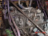
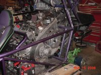
I’m finally wiring the 2 turbo Rx-1 motors in my dunebuggy and have some questions! Hoping to get some help, if you know the answer to just one question still I appreciate the Help Thanks in advance -Ed
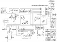
1)The Yellow/Black wire from the CDI to the Tach carries what signal at what RPM? (I am assuming a square wave frequency corresponding to RPM and if I had a running machine I would put a scope on it)
2)What is the Yellow/Green (Y/G) wire from the CDI to the multi-function meter for?
3)What is the Light green/green (Lg/G) wire from the CDI to the multi-function meter for?
4)What is the Green/Red (G/R) wire from the CDI to the multi-function meter for?
5)I will be removing the throttle switch (10) and carb switch (11): Does anyone know the best way to fake out the CDI as to not have any interruptions in the ign. System. I believe I would just short both switches.
Ed L
Veteran
TurboJamie
TY 4 Stroke God
Umm WOW can I get some of whatver you are on... That is Sick in so many ways.
Ed L
Veteran
I dont know how close you are but you are welcome to take all the readings you want off my running Rx-1.
Ed L
Veteran
I dont know how close you are but you are welcome to take all the readings you want off my running Rx-1.
Thanks I may be taking you up on that to verify, but thanks to Sledfvr, we believe the RX1 tach line (yellow/black) pluses 6 times per revolution. Seems strange from a 4 stroke 4 cylinder which fires 2 times per revolution, but they may have increased it for better resolution. In the computer I am using as my dash and data acquisition I will take the tach frequency x 60 for RPM /6 pulses per rev. or just frequency x 10.
I also figured out (by reading the manual) that both the throttle switch and carb switch need to be open to interupt the Ign. So if I short both of them I should have no problems.
I still have no clue what the 3 wires Yellow/Green (Y/G), Light green/green (Lg/G) and Green/Red (G/R) going to the gauge pod from the CDI are for? If anyone knows please speakup. Thanks -Ed

kinger
VIP Member
For those wires you can't figure out see if its attached to the handwarmer and thumb warmer circuit. When you adjust it shows up/down in the display. When I summarize mine I can try and take a reading for you while adjusting the warmers.
Ed L
Veteran
For those wires you can't figure out see if its attached to the handwarmer and thumb warmer circuit. When you adjust it shows up/down in the display. When I summarize mine I can try and take a reading for you while adjusting the warmers.
They are going to the gauge pod from the CDI only on the print. Though I wasn't aware that when you adjust it shows up/down in the display, so that might be some of them are for. I just don't want to be chasing something that I needed in my application, which is mainly Ing. Charging and some signal wiring. Thanks for pointing that out!
They are going to the gauge pod from the CDI only on the print. Though I wasn't aware that when you adjust it shows up/down in the display, so that might be some of them are for. I just don't want to be chasing something that I needed in my application, which is mainly Ing. Charging and some signal wiring. Thanks for pointing that out!
Looking at the wiring diagram, the best I can assume is that the Yellow/Green (Y/G) which goes from the CDI to the Multi-function Meter is the grip warmer display since the grip warmer has a yellow wire going to the CDI and the Light green/green (Lg/G) wire is the thumb warmer display since that has a light green wire going from the warmer to the CDI.
The Green/Red (G/R) wire looks to be the wire that tells the CDI when the oil is low since it goes from the CDI to a multi function meter with another wire red/black (R/B) that comes from the oil level switch. After the multi function meter, a wire goes to the warning light. When there is enough oil in the tank, there is no continuity and the light does not go on.
This project sounds awesome! Definitely need a video when it's running.
BTW, my wiring diagram from the 2003 RX-1 service manual looks different than the one you posted, mostly just the numbers.
Ed L
Veteran
Thanks Redrocket! I didn't notice the color similarities untill you pointed it out. Looks like I need not worry about the hand and thumb warmer displays.
Hope to have it running by this Memorial day, just about to start wiring everything, finishing up clutch gaurds heat shields, Carbor Fiber body panels and H2o/meth injection system which I will post pic's of soon. Thanks for taking the time to help out. -Ed
I was just going to wire the switch input into the computer for the low oil, as a warning light. But the green/Red wire has me thinking what the CDI does with a low oil signal, do I need to fake it out as to not shut anything down?The Green/Red (G/R) wire looks to be the wire that tells the CDI when the oil is low since it goes from the CDI to a multi function meter with another wire red/black (R/B) that comes from the oil level switch. After the multi function meter, a wire goes to the warning light. When there is enough oil in the tank, there is no continuity and the light does not go on.
Hope to have it running by this Memorial day, just about to start wiring everything, finishing up clutch gaurds heat shields, Carbor Fiber body panels and H2o/meth injection system which I will post pic's of soon. Thanks for taking the time to help out. -Ed

kinger
VIP Member
That wire just lights up the display on the gauge pod when the oil gets low, it doesn't shut anything down its a FYI only. Use the sender on the top of the oil can or just leave it unwired.
The apex has a low oil pressure shut down.
The apex has a low oil pressure shut down.
Ed L
Veteran
OK Thanks, then why would it go to the CDI and not just the display?That wire just lights up the display on the gauge pod when the oil gets low, it doesn't shut anything down its a FYI only.
That is how I intend to turn on my warning lightUse the sender on the top of the oil can.

kinger
VIP Member
Everything that goes into the gauge pod only comes from the CDI. Not real sure why though.
The display only uses 1 bar graph for 3 settings. Fuel, thumb and hand warmers. the computer displays fuel until you touch either thumb or hand warmer controls then goes back to fuel when done.
Ed L
Veteran
Help! I now have it all wired on both motors, but the main relay (4) will not turn on due to the Brown/white wire (the relay coil -) which connects to the CDI. I have power at the other Brown/white wire that powers the CDI from key and kill switch and it turns over. I am hoping someone has some ideas. Both the throttle switch and the carb switch are shorted Thanks -Ed
Similar threads
- Replies
- 5
- Views
- 635
- Replies
- 16
- Views
- 1K
- Replies
- 2
- Views
- 1K
- Replies
- 2
- Views
- 2K
-
This site uses cookies to help personalise content, tailor your experience and to keep you logged in if you register.
By continuing to use this site, you are consenting to our use of cookies.


