Richard Hodgins
Expert
- Joined
- Mar 5, 2019
- Messages
- 243
- Age
- 46
- Location
- Ottawa ontario
- Country
- Canada
- Snowmobile
- Yamaha powered CAT
Thanks Tcat for the detailed information on the installation!
Now, if you could please give us some tips on the wiring, that would be great! I read through this thread a few times, but, unless I somehow missed it, I'm still uncertain about the wiring to the diagnostic port. Also, where is the best place to pull power for the unit?
Thanks much!
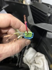
Here’s a pic of wiring the connector that communicates to the power steering unit. You can tap into the diagnostic port beside chaincase OR if If you have a 2019 and never with dumbshocks, you can use the lead for the smart shocks since it’s part of all the harnesses from 2019 and up. It’s just long enough to reach the power steering unit. This is what I did so very simple and no extra wiring, looks factory. There is a power wire there as well as the 2 Canbus wires.
The next plug is just power and ground. For power just tap into the main battery harness under the fuse box
Attachments
Last edited:

FYI, anyone who is or has to make a harness up to the diag port, the wires really should be a shielded/twisted pair. Twisted alone is probably good enough, shielded for that extra security. You don't want corrupt canbus messages flying around.


1nc 2000
Lifetime Member Tim
- Joined
- Feb 26, 2010
- Messages
- 3,048
- Location
- Marquette, MI
- Country
- USA
- Snowmobile
- Yamaha FX Nytro RTX SE
Then run an additional wire from the shielding to the ground. What gauge wire would you recommend? 20?FYI, anyone who is or has to make a harness up to the diag port, the wires really should be a shielded/twisted pair. Twisted alone is probably good enough, shielded for that extra security. You don't want corrupt canbus messages flying around.
YamaSpark
VIP Member
- Joined
- Sep 21, 2017
- Messages
- 104
- Location
- Greenfield, Minnesota
- Country
- USA
- Snowmobile
- 2016 SR VIPER S-TX 137 DX
Thanks for the info Richard, please give us an update as soon as you get it wired up and tested.Here’s a pic of wiring the connector that communicates to the power steering unit. You can tap into the diagnostic port beside chaincase OR if If you have a 2019 and never with dumbshocks, you can use the lead for the smart shocks since it’s part of all the harnesses from 2019 and up. It’s just long enough to reach the power steering unit. This is what I did so very simple and no extra wiring, looks factory. There is a power wire there the 2 Canbus wires.
The next plug is just power and ground. For power just tap into the main battery harness under the fuse box
So, the smart shock wiring is the same as the Canbus/diagnostic port?
Also, do you happen to have any pics of the eps motor mounted in place?
Thanks!
Then run an additional wire from the shielding to the ground. What gauge wire would you recommend? 20?
Yes, 20 awg is fine. Ground the shield on one end to avoid ground conflict issues. You want some form of high strand count hookup wire or connection wire so that it can handle vibration. You can purchase canbus cable from places like mcmaster-carr
Thanks for the info Richard, please give us an update as soon as you get it wired up and tested.
So, the smart shock wiring is the same as the Canbus/diagnostic port?
Also, do you happen to have any pics of the eps motor mounted in place?
Thanks!
Any canbus port will be the same from looking at the schematics.
YamaSpark
VIP Member
- Joined
- Sep 21, 2017
- Messages
- 104
- Location
- Greenfield, Minnesota
- Country
- USA
- Snowmobile
- 2016 SR VIPER S-TX 137 DX
For the main power I would just run a dedicated line to the battery with an inline 30 amp fuse, and a good ground, and call it a day. For the smaller connector, 2 wires will go to the diagnostic connector by the reverse actuator, and you can find switched power there too I believe for the 3rd wire.
For the main power in, wouldn't it be best to be switched, or does the small power wires from the can-bus/diagnostic connector energize the circuit in the eps motor? How many actual terminals are in the can-bus "in" connector on the motor?
Thanks!
The EPS motor needs a 30amp circuit straight from the battery through an inline 30amp fuse. The canbus connection I think just needs switched power to energize the local circuit.
Richard Hodgins
Expert
- Joined
- Mar 5, 2019
- Messages
- 243
- Age
- 46
- Location
- Ottawa ontario
- Country
- Canada
- Snowmobile
- Yamaha powered CAT
I don’t know what that is, but it’s NOT factory EPS
Richard Hodgins
Expert
- Joined
- Mar 5, 2019
- Messages
- 243
- Age
- 46
- Location
- Ottawa ontario
- Country
- Canada
- Snowmobile
- Yamaha powered CAT
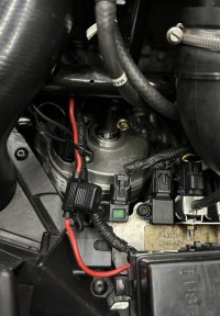
This is what the factory EPS looks like installed. You will notice the power lead I installed with 30amp inline fuse. Also the factory wiring harness that was meant for ATAC was used for the CANBUS communication .
I also just tested in garage after install: it works and no codes! I have a 2019 and QS3R shocks.
I also just tested in garage after install: it works and no codes! I have a 2019 and QS3R shocks.
Attachments
YamaSpark
VIP Member
- Joined
- Sep 21, 2017
- Messages
- 104
- Location
- Greenfield, Minnesota
- Country
- USA
- Snowmobile
- 2016 SR VIPER S-TX 137 DX
This is what the factory EPS looks like installed. You will notice the power lead I installed with 30amp inline fuse. Also the factory wiring harness that was meant for ATAC was used for the CANBUS communication .
I also just tested in garage after install: it works and no codes! I have a 2019 and QS3R shocks.
YES!! That's what I wanted to hear!
Thanks for the update & picture.
How many terminals are in the can bus "in" connector on the EPS motor (I assume three)?
Richard Hodgins
Expert
- Joined
- Mar 5, 2019
- Messages
- 243
- Age
- 46
- Location
- Ottawa ontario
- Country
- Canada
- Snowmobile
- Yamaha powered CAT
The CANBUS Connector has 8 terminals, but only 3 are used. That's why you need to refer to the wiring diagram to know WHICH ones to wire up. I believe Earthling or TCat100 may have posted that diagram, or you can get it from the CAT site. You need to source the connectors and also the wire leads related to those connectors. These are super small wires/terminal leads...I dont wear reading glasses but definitely needed them to do this work. lolYES!! That's what I wanted to hear!
Thanks for the update & picture.
How many terminals are in the can bus "in" connector on the EPS motor (I assume three)?
YamaSpark
VIP Member
- Joined
- Sep 21, 2017
- Messages
- 104
- Location
- Greenfield, Minnesota
- Country
- USA
- Snowmobile
- 2016 SR VIPER S-TX 137 DX
The CANBUS Connector has 8 terminals, but only 3 are used. That's why you need to refer to the wiring diagram to know WHICH ones to wire up. I believe Earthling or TCat100 may have posted that diagram, or you can get it from the CAT site. You need to source the connectors and also the wire leads related to those connectors. These are super small wires/terminal leads...I dont wear reading glasses but definitely needed them to do this work. lol
I have the connectors and wire leads, just waiting on the EPS motor and hardware!
So far, I've been unable to find the wiring diagram...
You don't happen to recall which terminals you used, do you?

Tcat100
Expert
Country Cat has the wiring diagramsThe CANBUS Connector has 8 terminals, but only 3 are used. That's why you need to refer to the wiring diagram to know WHICH ones to wire up. I believe Earthling or TCat100 may have posted that diagram, or you can get it from the CAT site. You need to source the connectors and also the wire leads related to those connectors. These are super small wires/terminal leads...I dont wear reading glasses but definitely needed them to do this work. lol

2022 Snowmobile Wiring Diagrams
Deleted..I don’t know what that is, but it’s NOT factory EPS
Similar threads
- Replies
- 5
- Views
- 1K
- Replies
- 19
- Views
- 5K
-
This site uses cookies to help personalise content, tailor your experience and to keep you logged in if you register.
By continuing to use this site, you are consenting to our use of cookies.