marpolsdofer
TY 4 Stroke Guru
When people first look or get a Base Model Phazer there are a few question that arise. One of the most common I think are, "Does it have Reverse?". Then when they find out it does not they ask, "Can it be added later?"
I here to tell you it CAN BE DONE without having to spend well more then $1000 and trying to track down the Reverse components. Such that of the drive shafts, gear case, servo, control/display pod, and wire harness/repining. LOL I sound like a infomercial!!!! Bellow will be pics, descriptions, and instructions.
So what do you need?
You a power source such as your battery or you can tap in to some thing else then directly from the battery. This is where you have to go find something. Get a a whole new shaft, gears/case, and servo (that's over $1000 alone) or get a OLD one (I have a used spare, got some one who wants it covered!") ). Other stuff that is easy to find- 6 wires and different size (small and large) quick connects (flat type female end). The quick connects are not needed you can cut into the Sub Harness for the Servo or solder them. Last thing you need is a Double Pole Double Throw (DPDT) Toggle Switch. It can be ON-OFF-ON or ON-ON.
). Other stuff that is easy to find- 6 wires and different size (small and large) quick connects (flat type female end). The quick connects are not needed you can cut into the Sub Harness for the Servo or solder them. Last thing you need is a Double Pole Double Throw (DPDT) Toggle Switch. It can be ON-OFF-ON or ON-ON.
Note - Add electrical tape around connections and around the the top of the switch to prevent short circuits with water. A inline fuse might be a good idea.
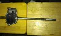
Pic 01 - This is the main components you need the have a operable Drive and Reverse System. The Drive Shafts (jack-shafts), Gears, Case, and servo.
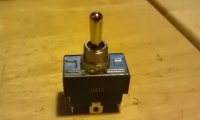
Pic 02 - Normal DPDT Toggle Switch, you can find this at any hardware store.
Pic 03 - What the current needs to be to switch from Drive to Reverse or vise virsa.
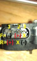
Pic 04 - The wiring on the on the DPDT should be like so indicated on the photo. Remember when you throw the switch the handle is pointed opposite of the wiring. Exp - You wire D/R; wiring D is on the north side of the switch and wiring R on the south side. The switch would be thrown to the south for Drive. Just to be clear that you know it should work. How you want to be pointing while its on the sled is up to the owner. Also dont forget the a switch usually has a indent so you can make a notch to stop it from rotating.
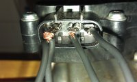
Pic 05 and Pic 06 - Places you can tap in to for the wiring of the sub-harness to prevent damaging to the Servo pins.
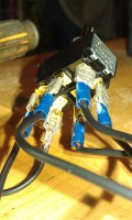
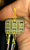
Pic 07 and Pic 08 - Note Pic 07 that Pin #1 has two wires connected to it. This is becaues it needs and Positive or Negative voltage depending if you need Drive or Reverse. These are examples (and temporary) of how I connected and wired it.
Pic 09 -A example of how it will look afterwords. I drawn colors on the wires to identify the leads, etc.
Red-Positive for Drive
Black-Negative for Drive
Blue-Positive for Reverse
Yellow-Negative for Reverse
White-Positive 12v
Green-Negative 12v
I here to tell you it CAN BE DONE without having to spend well more then $1000 and trying to track down the Reverse components. Such that of the drive shafts, gear case, servo, control/display pod, and wire harness/repining. LOL I sound like a infomercial!!!! Bellow will be pics, descriptions, and instructions.
So what do you need?
You a power source such as your battery or you can tap in to some thing else then directly from the battery. This is where you have to go find something. Get a a whole new shaft, gears/case, and servo (that's over $1000 alone) or get a OLD one (I have a used spare, got some one who wants it covered
). Other stuff that is easy to find- 6 wires and different size (small and large) quick connects (flat type female end). The quick connects are not needed you can cut into the Sub Harness for the Servo or solder them. Last thing you need is a Double Pole Double Throw (DPDT) Toggle Switch. It can be ON-OFF-ON or ON-ON.Note - Add electrical tape around connections and around the the top of the switch to prevent short circuits with water. A inline fuse might be a good idea.
Pic 01 - This is the main components you need the have a operable Drive and Reverse System. The Drive Shafts (jack-shafts), Gears, Case, and servo.
Pic 02 - Normal DPDT Toggle Switch, you can find this at any hardware store.
Pic 03 - What the current needs to be to switch from Drive to Reverse or vise virsa.
Pic 04 - The wiring on the on the DPDT should be like so indicated on the photo. Remember when you throw the switch the handle is pointed opposite of the wiring. Exp - You wire D/R; wiring D is on the north side of the switch and wiring R on the south side. The switch would be thrown to the south for Drive. Just to be clear that you know it should work. How you want to be pointing while its on the sled is up to the owner. Also dont forget the a switch usually has a indent so you can make a notch to stop it from rotating.
Pic 05 and Pic 06 - Places you can tap in to for the wiring of the sub-harness to prevent damaging to the Servo pins.
Pic 07 and Pic 08 - Note Pic 07 that Pin #1 has two wires connected to it. This is becaues it needs and Positive or Negative voltage depending if you need Drive or Reverse. These are examples (and temporary) of how I connected and wired it.
Pic 09 -A example of how it will look afterwords. I drawn colors on the wires to identify the leads, etc.
Red-Positive for Drive
Black-Negative for Drive
Blue-Positive for Reverse
Yellow-Negative for Reverse
White-Positive 12v
Green-Negative 12v
Attachments


Jeffz
VIP Member
- Joined
- Feb 3, 2010
- Messages
- 600
- Reaction score
- 8
- Points
- 1,013
- Location
- Cresco, Iowa
- Country
- USA
- Snowmobile
- 2008 Yamaha Nytro RTX 40th
2007 Phazer "RTX"
Awesome info! Thanks!
yamaha1973
TY 4 Stroke Master
- Joined
- Nov 27, 2011
- Messages
- 1,288
- Reaction score
- 14
- Points
- 743
- Location
- St. Peter Minnesota
- Country
- USA
- Snowmobile
- 2014 Viper XTX SE
great write up!


Mooseman
I'm not all knowing. Post your question in forum.
- Joined
- Nov 3, 2009
- Messages
- 4,109
- Reaction score
- 1,078
- Points
- 1,733
- Location
- Greely, Ontario
- Country
- Canada
- Snowmobile
- '07 Venture MP (gone)
'07 Phazer FX (gone)
'09 Phazer GT (gone)
'10 RS Venture GT (My current ride)
'10 Nytro FX (son's)
- LOCATION
- Greely, ON Canada
Maybe just one caveat to add: since the shifting is not controlled by the ECM, it will not limit the engine speed if it is not properly engaged. You should possibly add some LEDs to the forward and reverse sensor switches on the gear box to indicate when it has in fact engaged. Otherwise the gears can get damaged.
marpolsdofer
TY 4 Stroke Guru
Yea that part is on the other forum. Who ever does it needs to avoid shifting at a high RPM. Only way to tell with this is to give the engine a bit of gas. If you have trouble. start out the belt deflection and chin case tension could always give the rear end a quick tug upward.
Right now I would be trying to figure out how to pass a current to the sensors. Is the Actuator Arm plastic or metal? If its metal I would think the sensors get power from the Servo.
Right now I would be trying to figure out how to pass a current to the sensors. Is the Actuator Arm plastic or metal? If its metal I would think the sensors get power from the Servo.
Jeffz
VIP Member
- Joined
- Feb 3, 2010
- Messages
- 600
- Reaction score
- 8
- Points
- 1,013
- Location
- Cresco, Iowa
- Country
- USA
- Snowmobile
- 2008 Yamaha Nytro RTX 40th
2007 Phazer "RTX"
Since it would shift at any RPM it would probably be a good idea to put the switch somewhere where you will won't hit it by accident.
Mooseman
I'm not all knowing. Post your question in forum.
- Joined
- Nov 3, 2009
- Messages
- 4,109
- Reaction score
- 1,078
- Points
- 1,733
- Location
- Greely, Ontario
- Country
- Canada
- Snowmobile
- '07 Venture MP (gone)
'07 Phazer FX (gone)
'09 Phazer GT (gone)
'10 RS Venture GT (My current ride)
'10 Nytro FX (son's)
- LOCATION
- Greely, ON Canada
I would use push buttons instead as it would need an actual conscious held action to actuate. For the sensor switches they contact to ground when actuated so you would just need a positive to the LEDs to work.
The actuator (or shifter fork) is metal but the switch get its ground from the gear box itself. You could push it with a piece of wood and it would still work.
The actuator (or shifter fork) is metal but the switch get its ground from the gear box itself. You could push it with a piece of wood and it would still work.
2stroken
Expert
Sweet write up!
Yammer on the Rock
Veteran
- Joined
- Mar 16, 2008
- Messages
- 36
- Reaction score
- 8
- Points
- 858
- Location
- NL
- Country
- Canada
- Snowmobile
- Venture Lite
Excellent write-up and a project for later. I have been having issues with the infamous lashing green light so looks like a way out. I pulled the servo and bench tested it and everything was great. Today I put the servo back on and tested it on the machine with jumpers and battery and it shifted great. Feeling my headache was over I put everything back together fired it up and it worked for five minutes then got the flashing green light and nothing. Disconnected at the plug/junction near the rotor and energized the servo again with the battery and it shifted. Hooked everything back up and it works on the dash pod switches. Starting to think it's intermittent up in the dash pod and switches there so the next step is this project. Really not excited on the prospect of the flashing green 50km back in the country.
Dan Lance
VIP Member
- Joined
- Mar 5, 2019
- Messages
- 68
- Reaction score
- 25
- Points
- 473
- Location
- Eagle River Ak
- Country
- USA
- Snowmobile
- nytro,apex,summit,rs vneture,phazer
If you splice the three wires into the existing harness as described above, but use diodes upstream at the splice connections into the factory harness, the green D, yellow R, and reverse beeper all work perfectly.
Last edited:
Similar threads
- Replies
- 5
- Views
- 4K
- Replies
- 6
- Views
- 3K
- Replies
- 3
- Views
- 2K
-
This site uses cookies to help personalise content, tailor your experience and to keep you logged in if you register.
By continuing to use this site, you are consenting to our use of cookies.