- Joined
- Apr 17, 2003
- Messages
- 5,538
- Reaction score
- 1,398
- Points
- 2,003
- Location
- Menno, SD
- Website
- www.ulmerracing.com
- Country
- USA
- Snowmobile
- 2014 Yamaha SR Viper LTX, 2014 Yamaha SR Viper RTX SE, 2015 Yamaha SR Viper MTX SE 162 (turbo), 2015 Yamaha SR Viper MTX SE 153
- LOCATION
- Menno, SD
- WEBSITE
- www.ulmerracing.com
The bellmouths will be better than flat mounted to the base of the flange. The bellmouth will catch the air as it bounces off the back wall, for lack of better terms. You need volume to help reduce air speed and dissipate heat. A small volume high speed intake will run higher intake temps and less horsepower per lb of boost.
Here is my plenum redesign.
Due to the fact the apex TB rack doesn't sit centered in the frame, Ive had to offset the inlet to the plenum as can be seen here.
(Will add more reinforcement ribs once the final size is determined.)
Will this adversely affect uniform flow to each cyl?

Due to the fact the apex TB rack doesn't sit centered in the frame, Ive had to offset the inlet to the plenum as can be seen here.
(Will add more reinforcement ribs once the final size is determined.)
Will this adversely affect uniform flow to each cyl?


earthling
Lifetime Member
- Joined
- Dec 1, 2017
- Messages
- 2,065
- Reaction score
- 2,023
- Points
- 1,263
- Location
- Ontario
- Country
- Canada
- Snowmobile
- 2021 SRX
2006 ATTAK
Here is my plenum redesign.
Due to the fact the apex TB rack doesn't sit centered in the frame, Ive had to offset the inlet to the plenum as can be seen here.
(Will add more reinforcement ribs once the final size is determined.)
Will this adversely affect uniform flow to each cyl?
View attachment 169294
Boost hides some of the asymmetry but your primary airflow is going to be better for the closer cylinders. (shorter from intake to output). The question is how much. Under boost it probably is minimized.
If you are concerned what you can do is offset the angle slightly of the input tube so it is more biased (canted) towards the farthest tube, the other thing I have seen done is to put a hump inside the plenum in front of the shortest run to make the air flow around the hump which makes the lengths more equal, equalizing the flows between the shortest and longest runs. Its hard to make improvements however without CFD modeling or trial and error.
If you want to give yourself more confidence, print out the manifold and use a blower motor to simulate the turbo and measure the outputs.
Also, what others have done.
kinger
VIP Member
- Joined
- Jan 17, 2005
- Messages
- 7,422
- Reaction score
- 1,556
- Points
- 1,963
- Location
- Clear Lake, IA
- Website
- www.piergenius.com
I think you're fine on that asymmetry. I look at a lot of car stuff and never seen that to be a huge issue for anyone trying to make 10lbs of crap fit in tight spaces. It is pressurized air so it will go EVERYWHERE.
I tried to angle the outlet but i dont think that will help much.. Probably good enough for version 1.


Regarding this idle air circuit, I suppose it is run back into the plenum as otherwise there will be an air leak under boost?
Could a 1 way check valve be used to stop the boost leak? Then i would leave the checkvalve to atmospheric, I would do this as it would be cleaner and 1 less hose to connect to the plenum each time. Or should i just run it to the plenum? If so I would 3dprint a y piece then connect a piece of large vac hose to it so it is only 1 hose and not 2 little short hoses like seen on the kits where the intercooler mounts directly to the TBs.

To fit the nytro oil tank upfront, I have had to notch out the crossmember. It now attaches from behind to the side frame. I will then use the lower holes that cat uses to fab a new crossbar, as it must also be bent, to clear the steering and the nytro tank. I made a 3dprinted rubber bracket that slides down into a bolt welded to the bottom bracket to hold the tank down at the bottom. This is done so it can slide in at the bottom, no wrench needed. Once secured to the top bracket, it wont be able to come out.


I was also thinking of swapping the sidewinder stator into the apex if it works for increased output. It looks like the apex trigger wheel uses less teeth than the sidewinder, so I am not sure if the flywheel will also swap over?
Regarding this idle air circuit, I suppose it is run back into the plenum as otherwise there will be an air leak under boost?
Could a 1 way check valve be used to stop the boost leak? Then i would leave the checkvalve to atmospheric, I would do this as it would be cleaner and 1 less hose to connect to the plenum each time. Or should i just run it to the plenum? If so I would 3dprint a y piece then connect a piece of large vac hose to it so it is only 1 hose and not 2 little short hoses like seen on the kits where the intercooler mounts directly to the TBs.
To fit the nytro oil tank upfront, I have had to notch out the crossmember. It now attaches from behind to the side frame. I will then use the lower holes that cat uses to fab a new crossbar, as it must also be bent, to clear the steering and the nytro tank. I made a 3dprinted rubber bracket that slides down into a bolt welded to the bottom bracket to hold the tank down at the bottom. This is done so it can slide in at the bottom, no wrench needed. Once secured to the top bracket, it wont be able to come out.
I was also thinking of swapping the sidewinder stator into the apex if it works for increased output. It looks like the apex trigger wheel uses less teeth than the sidewinder, so I am not sure if the flywheel will also swap over?
sxr70001
Lifetime Member
- Joined
- Dec 4, 2010
- Messages
- 1,155
- Reaction score
- 770
- Points
- 1,438
- Location
- Michigan
- Country
- USA
- Snowmobile
- Sidewinder LTX SE
SR Viper RTX SE
Looks good to me. I am always amazed by the talented people we have on this site.
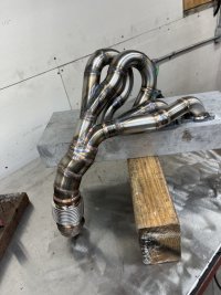
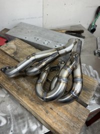
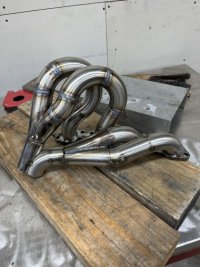
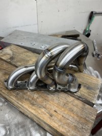
Some updates... getting there. header primaries half done, thanks to @kennyspec. I couldnt get 1.75 elbows so i went with 1.5. The difference to 1.75 dia is the wall thickness of .065. It looks like the alpine header i had on there was also 1.5. It should spool up quick.


flowmaster 1-2 for dual exhaust. will be angled down and cut once in the final position.

I also want to run the meth direct port with the AEM v3 nozzle. However that would mean a 250cc jet in each cyl, 1000cc/min total on the max setting. I am not sure how much lower you can go, 50% maybe? thats still 500cc/min and may be too much ? maybe i will just run 1 500cc injector and then can dial down to 250 to start?
At 500cc thats 1 litre consumed every 2 minutes, with a 4 litre tank you only have 8 minutes of WOT fun. I was planning to print a polypropolene tank above the clutch guard, and have an integrated coolant overflow to save space and be able to make the tank as big as possible, but I dont know I want to hold more than 4 litres of 50/50 water meth above my clutch????
I would also need the dynojet timing module for 2step and timing changes due to the meth. Does anyone have one for sale for the apex motor?

flowmaster 1-2 for dual exhaust. will be angled down and cut once in the final position.
I also want to run the meth direct port with the AEM v3 nozzle. However that would mean a 250cc jet in each cyl, 1000cc/min total on the max setting. I am not sure how much lower you can go, 50% maybe? thats still 500cc/min and may be too much ? maybe i will just run 1 500cc injector and then can dial down to 250 to start?
At 500cc thats 1 litre consumed every 2 minutes, with a 4 litre tank you only have 8 minutes of WOT fun. I was planning to print a polypropolene tank above the clutch guard, and have an integrated coolant overflow to save space and be able to make the tank as big as possible, but I dont know I want to hold more than 4 litres of 50/50 water meth above my clutch????
I would also need the dynojet timing module for 2step and timing changes due to the meth. Does anyone have one for sale for the apex motor?
Last edited:
kennyspec
Expert
- Joined
- Sep 30, 2009
- Messages
- 327
- Reaction score
- 88
- Points
- 738
- Location
- stonewall, manitoba
- Country
- Canada
- Snowmobile
- nytro

kennyspec
Expert
- Joined
- Sep 30, 2009
- Messages
- 327
- Reaction score
- 88
- Points
- 738
- Location
- stonewall, manitoba
- Country
- Canada
- Snowmobile
- nytro
What's the reasoning for all the mufflers? Looks like a headache for the fabricator........
kinger
VIP Member
- Joined
- Jan 17, 2005
- Messages
- 7,422
- Reaction score
- 1,556
- Points
- 1,963
- Location
- Clear Lake, IA
- Website
- www.piergenius.com
Some updates... getting there. header primaries half done, thanks to @kennyspec. I couldnt get 1.75 elbows so i went with 1.5. The difference to 1.75 dia is the wall thickness of .065. It looks like the alpine header i had on there was also 1.5. It should spool up quick.
View attachment 169387
View attachment 169388
View attachment 169389
flowmaster 1-2 for dual exhaust. will be angled down and cut once in the final position.
View attachment 169390
I also want to run the meth direct port with the AEM v3 nozzle. However that would mean a 250cc jet in each cyl, 1000cc/min total on the max setting. I am not sure how much lower you can go, 50% maybe? thats still 500cc/min and may be too much ? maybe i will just run 1 500cc injector and then can dial down to 250 to start?
At 500cc thats 1 litre consumed every 2 minutes, with a 4 litre tank you only have 8 minutes of WOT fun. I was planning to print a polypropolene tank above the clutch guard, and have an integrated coolant overflow to save space and be able to make the tank as big as possible, but I dont know I want to hold more than 4 litres of 50/50 water meth above my clutch????
I would also need the dynojet timing module for 2step and timing changes due to the meth. Does anyone have one for sale for the apex motor?
View attachment 169391
I will have more info soon as I am just playing with meth but I went pro meth kit and bought 2.5 gallon/hour nozzles times 4. That is roughly a 630 cc/min nozzle and I feel its still way too much water just playing with my set up I can drain a half gallon of distilled water in like 2 mins.
Also I have the most sophisticated ECU running it, and one of the most expensive solenoids and I am disappointed with the result thus far. At 20 hz my solenoid at under 20% does nothing, no spray. At 20% its a LOT of water, at 75% it wont spray any more then at 100% duty cycle so that means there is no "turning it down" if you are using a larger nozzle. Anything in between without measuring I can only see a little change in volume. I could be wrong too, this is my first meth experiment on any motor in my life. It is spread over 4 nozzles so maybe its just impossible to see in my rudimentary testing.
REAL rough generally you can 10-12 psi of boost on same fuel with Meth AND 10-12 degrees of timing. I will test this for sure on my apex but at least its a start.
I would NOT spray pre-intercooler, that is what forced me into the direct port. I suspect to do it right you will need to do that as well and with AEM nozzles they are designed to feed much larger engines with ONE nozzle not 4 so you would likely flood it and bend a rod with 4 that large. You need to be closer to 160 cc/min X 4 like mine. I will share and have data before you, it may be invaluable for your build.
Dan Lance
VIP Member
- Joined
- Mar 5, 2019
- Messages
- 68
- Reaction score
- 25
- Points
- 328
- Location
- Eagle River Ak
- Country
- USA
- Snowmobile
- nytro,apex,summit,rs vneture,phazer
Thats where the aquamist nozzles shine. Small and very foggy
kennyspec
Expert
- Joined
- Sep 30, 2009
- Messages
- 327
- Reaction score
- 88
- Points
- 738
- Location
- stonewall, manitoba
- Country
- Canada
- Snowmobile
- nytro
Wheres the updates to this?
mulot30th
Lifetime Member
- Joined
- Jul 7, 2007
- Messages
- 1,634
- Reaction score
- 2
- Points
- 1,073
- Website
- youtube.com
- Country
- Canada
- Snowmobile
- 2023 thundercat
apex mountain crracing 174
apex blower 136 for asphalt racing
osp drag race sled (apex engine based)
There is some serious R&D here
Any update onnhow this project went ?
Any update onnhow this project went ?
Similar threads
- Replies
- 9
- Views
- 3K
- Replies
- 1
- Views
- 700
-
This site uses cookies to help personalise content, tailor your experience and to keep you logged in if you register.
By continuing to use this site, you are consenting to our use of cookies.