rxrider
Jan-Ove Pedersen
- Joined
- Apr 25, 2003
- Messages
- 7,355
- Age
- 60
- Location
- Lakselv - 70N & 25E
- Country
- Norway
- Snowmobile
- 2014 Phazer XTX, 2013 Phazer RTX, 2008 Apex RTX, 2007 Warrior, 2006 Attak
Thanks guys ")
I'm back LOL
Gotta study how to measure valve lash/clearance, never done it before so I have some reading to do. Will also invite my friend Mikkel (the auto mechanic) to guide me thru the measuring process.
I'm back LOL
Gotta study how to measure valve lash/clearance, never done it before so I have some reading to do. Will also invite my friend Mikkel (the auto mechanic) to guide me thru the measuring process.
rxrider
Jan-Ove Pedersen
- Joined
- Apr 25, 2003
- Messages
- 7,355
- Age
- 60
- Location
- Lakselv - 70N & 25E
- Country
- Norway
- Snowmobile
- 2014 Phazer XTX, 2013 Phazer RTX, 2008 Apex RTX, 2007 Warrior, 2006 Attak
Update September 18. - Measuring valve clearance (or valve lash).
Have been studying valve clearance measuring and cam timing the last few days.
This evening I started measuring the valve clearance. Unfortunately my feeler blades goes in 0.05 millimeter increments. Steps are a little too big to give a correct reading, but accurate enough to get me within spec.
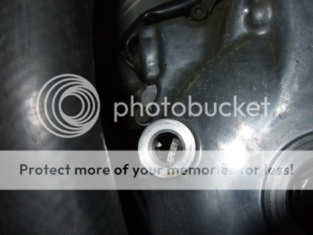
First step, rotate crank clockwise until the #4 piston is at TDC and the timing marks behind the timing plug lines up like shown in the picture.

Bummer.... I'm 360 off ....hahaha
After turning the crank another 360 degrees clockwise I ended up at the #4 TDC on the compression stroke.
Measure the valves on the cylinder where the lobes are facing away from each other (TDC at compression stroke), then turn the crank 180 degrees clockwise and measure the next valves where the piston is at TDC on it's compression stroke. Then another 180 deg CW, measure. Then another 180 and measure, you're done.
Specs for the intake valve clearance are 0.11-0.20 millimeters.
Specs for the exhaust valve clearance are 0.21-0.25 millimeters.
Maybe I'm not smart enough to follow the guidance in the Service Manual but I was not able to do the measurements by the book. Anyway.. I did it may way to say it with "old blue eyes".
Here's the #s from the measurements. I did the procedure twice to make sure I could duplicate the #s, and I did
As you can see, the clearance for the exhaust valves are perfect except for the #1 cylinder. Running a turbo or super clearance shall be at the higher end of specs.
The intake valve clearance are mostly lower than spec which is not a good thing, I will have to adjust all valves on the intake side.
I'm going to order a set of original Yamaha valve clearance feeler blades, they go in 0.02 millimeter increments.
Have been studying valve clearance measuring and cam timing the last few days.
This evening I started measuring the valve clearance. Unfortunately my feeler blades goes in 0.05 millimeter increments. Steps are a little too big to give a correct reading, but accurate enough to get me within spec.
First step, rotate crank clockwise until the #4 piston is at TDC and the timing marks behind the timing plug lines up like shown in the picture.
Bummer.... I'm 360 off ....hahaha
After turning the crank another 360 degrees clockwise I ended up at the #4 TDC on the compression stroke.
Measure the valves on the cylinder where the lobes are facing away from each other (TDC at compression stroke), then turn the crank 180 degrees clockwise and measure the next valves where the piston is at TDC on it's compression stroke. Then another 180 deg CW, measure. Then another 180 and measure, you're done.
Specs for the intake valve clearance are 0.11-0.20 millimeters.
Specs for the exhaust valve clearance are 0.21-0.25 millimeters.
Maybe I'm not smart enough to follow the guidance in the Service Manual but I was not able to do the measurements by the book. Anyway.. I did it may way to say it with "old blue eyes".
Here's the #s from the measurements. I did the procedure twice to make sure I could duplicate the #s, and I did
As you can see, the clearance for the exhaust valves are perfect except for the #1 cylinder. Running a turbo or super clearance shall be at the higher end of specs.
The intake valve clearance are mostly lower than spec which is not a good thing, I will have to adjust all valves on the intake side.
I'm going to order a set of original Yamaha valve clearance feeler blades, they go in 0.02 millimeter increments.
rxrider
Jan-Ove Pedersen
- Joined
- Apr 25, 2003
- Messages
- 7,355
- Age
- 60
- Location
- Lakselv - 70N & 25E
- Country
- Norway
- Snowmobile
- 2014 Phazer XTX, 2013 Phazer RTX, 2008 Apex RTX, 2007 Warrior, 2006 Attak
Update September 19. - Removing cam shafts. Removing cylinder head. Removing and documenting valve shims. Installing ARP 10 millimeter hardened head studs.
With everything in the way removed from the sled and the valve train cover removed from the engine, I will now show you how to remove the cam shafts and so on as said in the post header. Here we go.
First step is to unwind the cam chain tensioner. This is done by removing the 10 millimeter bolt covering the cam chain tensioner release/activate mechanism. Use a medium sized flat screwdriver and turn the screw behind the 10 millimeter bolt clockwise to release pressure on the chain, make sure the screw didn't jump back to the activated setting. The cam chain tensioner have released pressure on the cam chain and you will be able to free the cams from the chain.
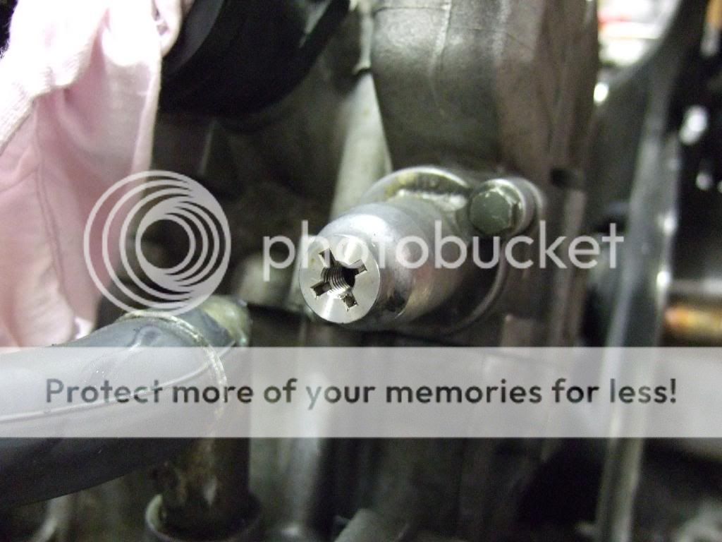
Next is securing the cam chain so it won't fall into the engine by accident.
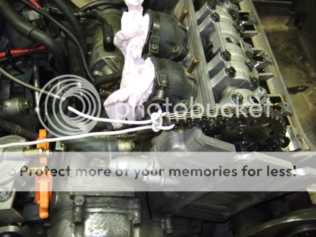
Start by removing the exhaust cam. Unscrew the cam cap bolts in small increments to release the pressure from the valve springs evenly to avoid bending the cam shaft. The cam caps may stick to the cam and the cam shafts may stick to the cylinder head, to get them loose tap gently on the cam sprocket with a rubber mallet or any rubber covered tool you may have, this will make the caps and cams jump loose.
CAUTION: Tap the cam caps loose as early as possible with the bolts barely loosened. WHY? if you remove the bolts and then tap, the cam and cam caps will come flying out of the cylinder head, NOT GOOD.
The exhaust cam can be a little tricky to get loose from the cam chain. Pull the exhaust cam a little to the rear on the right end side, now you will be able to move the sprocket forward in behinde the left side of the intake cam sprocket, lift the right side of the camshaft up a little and you should be able to free the exhaust cam shaft from the chain.
It's always a good idea to lay out the cam shafts and parts on a plate excactly as they was installed in the cylinder head to avoid installing them out of order on assemby. A few of the parts are looking the same but are not the same part # so be causious that every part goes back the same place they came out from.
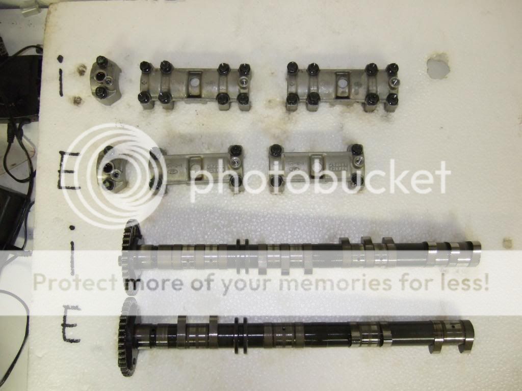
The routine of removing the intake cam shaft is the same as for the exhaust cam. Only difference, it's fairly easy to free it from the cam chain
CAUTION: Before loosening the cylinder head nuts make sure you have drained engine oil and coolant from the system or else you will make a flood of coolant and oil everywhere, and you will have coolant inside the crank case as well, NOT GOOD.
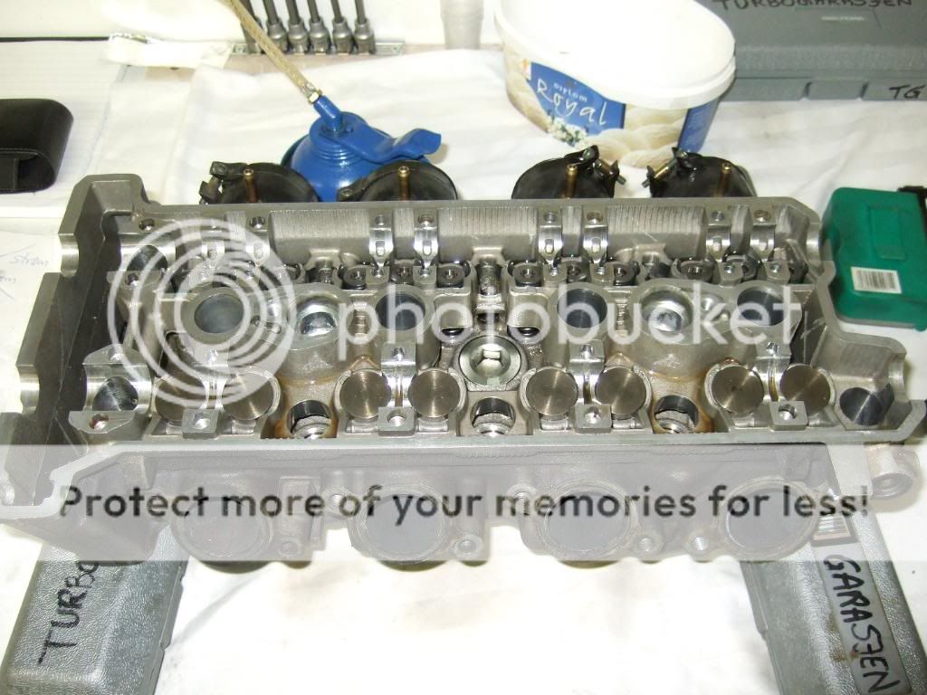
With the cams out of the way and the cam chain secured. I moved on to remove the cylinder head. First step is to remove the 2 #5 Allen bolts on the outside left on the cylinder head. Now to the 10 #8 Allen nuts inside the cylinderhead (one of them is actually outside the engine). Start by loosening the nuts just barely, loosen them in a star pattern starting at one of the "corners". Repeat the star pattern loosening the nuts a little of the time until the nuts are loose, remove them from the cylinder head.
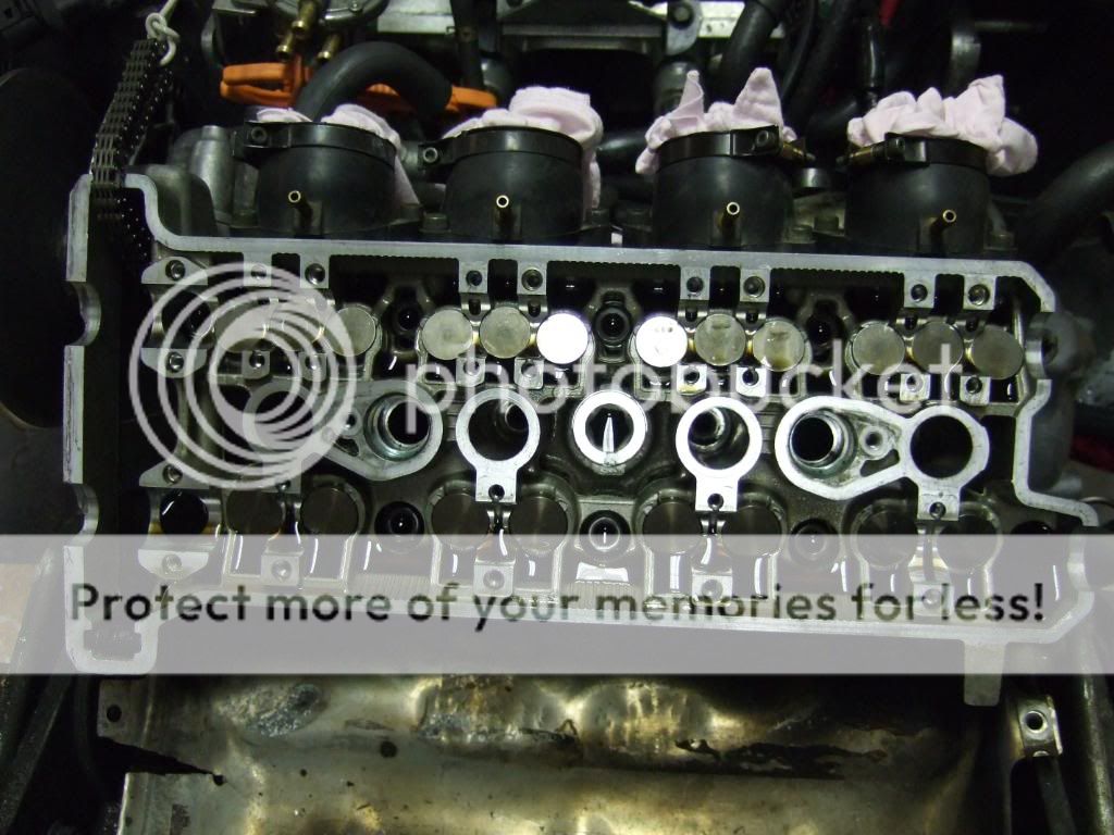
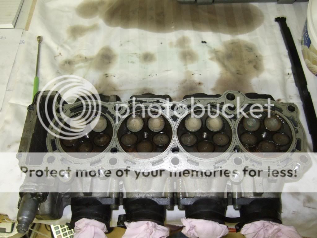
To get the cylinder head loose from the cylinder block you will have to make a firm grip on the cylinder head and make a abrupt pull, this will make the cylinder head slip the gasket. If you have a friend present now is the time for him/her to help you securing the cam chain while you are lifting the cylinder head away from the engine. With the cylinder head out, secure the cam chain. Place the cylinder head on a flat and clean surface.
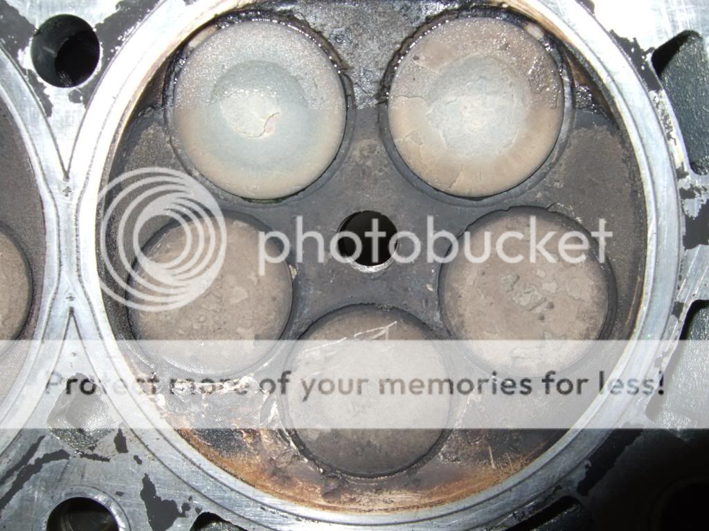
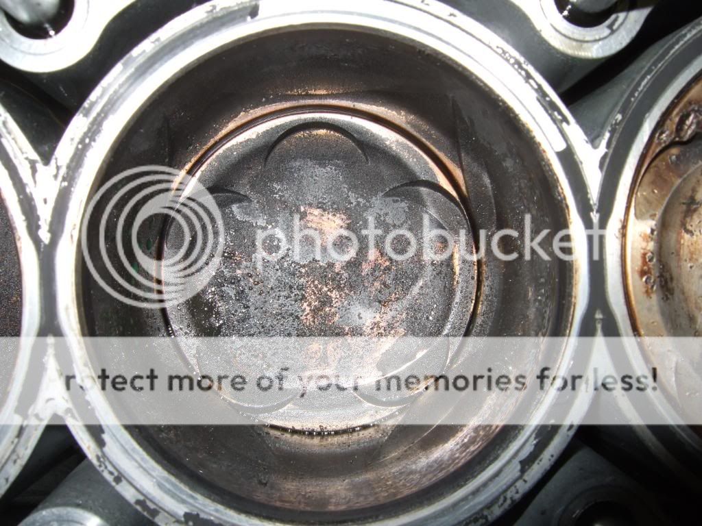
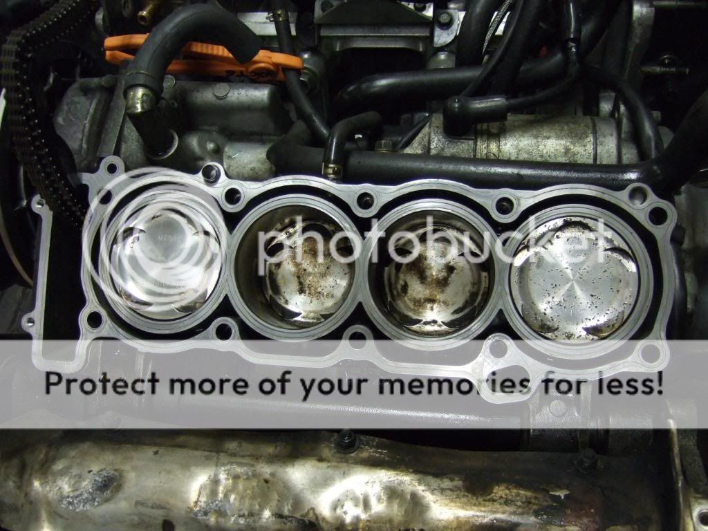
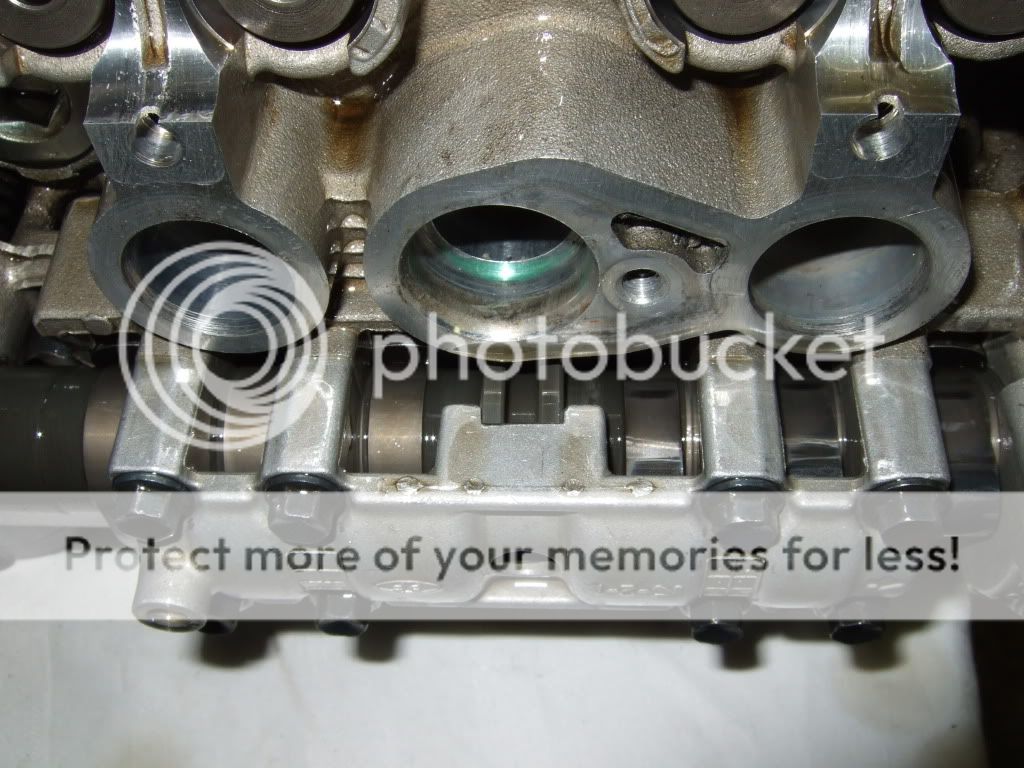
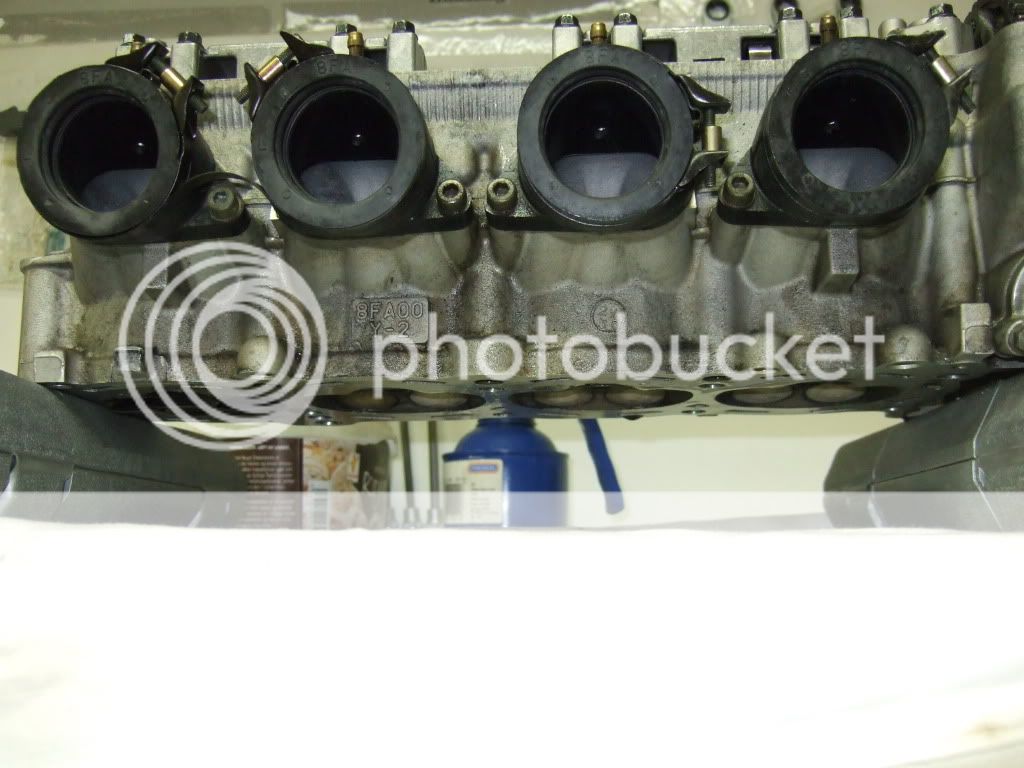
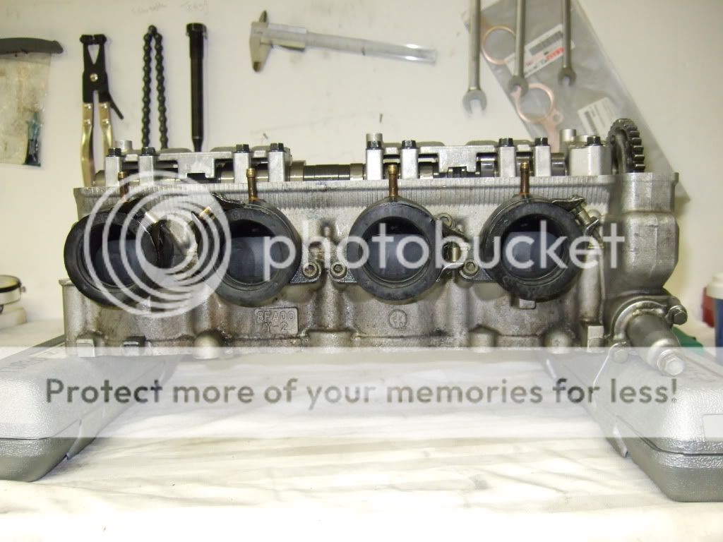
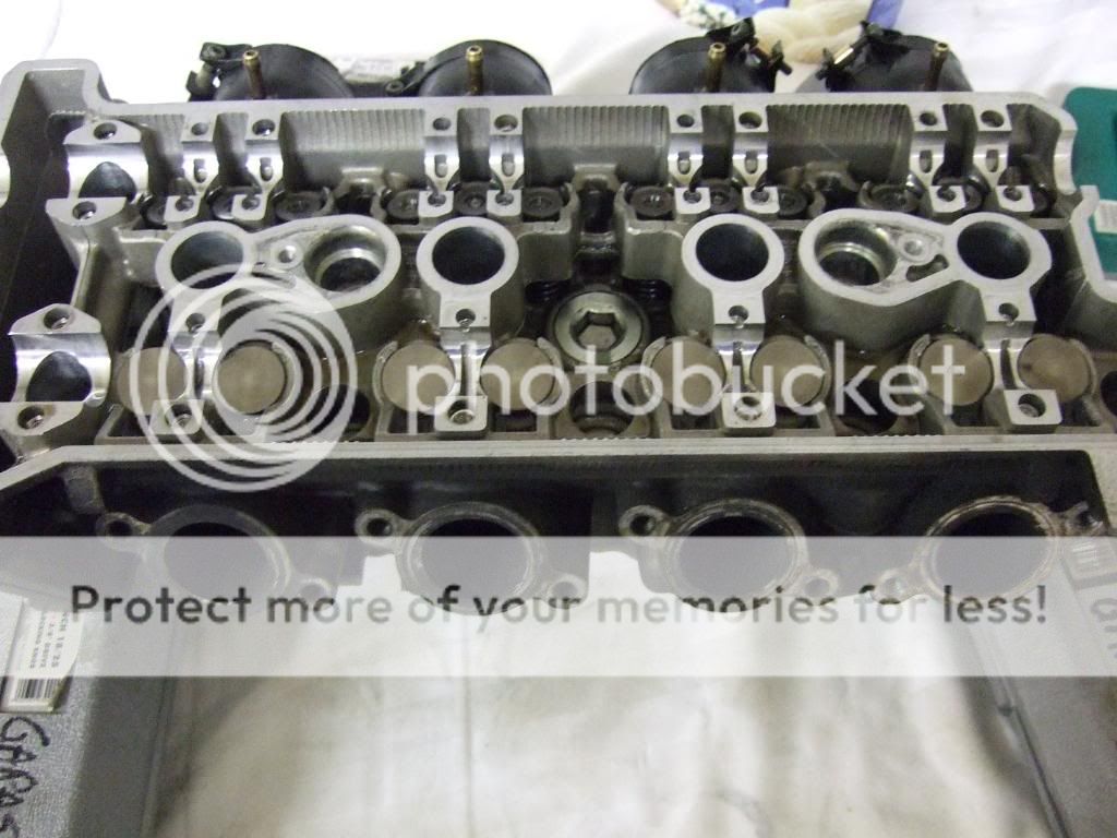
Here's what my combustion chambers looks like. There is some buildup of residues on the valves and combustion chamber walls. Pistons are full of tar like carbon residure that are easily wiped away by applying some gasket remover to it. There are signs of detonation in combustion chamber 2 and 4.
CC #1 - looks fine, I have been running at 11.2 AFRs at WOT last season, both the plugs, cylinder head CCs and pistons verifies the AFR readings.
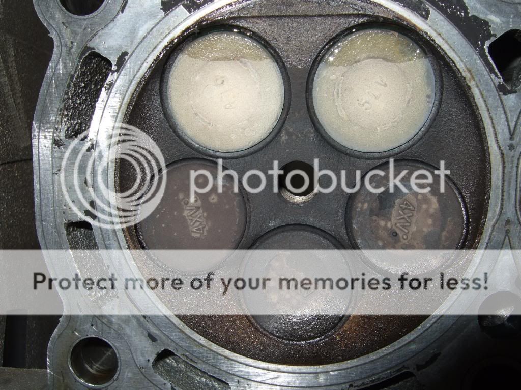
CC #2 - signs of detonation down and to the right in the pic.
CC #3 - prestine exept for the residure and a slight gasket failure to the left.
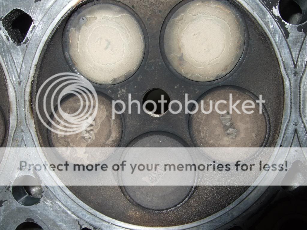
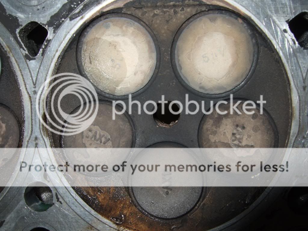
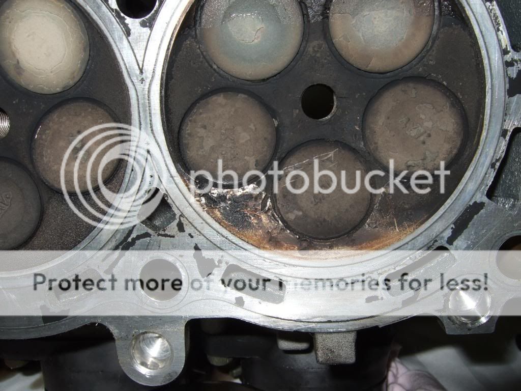
CC #4 - detonation has reared it's ugly head in cylinder #4 no doubt. Our engines typically detonates at the intake side of the CC, here's the evidence.
A closer look at CC #4
Piston #1 - other than the carbon buildup the piston is prestine, no deformation or sign of detonation.
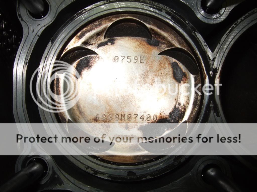
Piston #2 - signs of detonation on the edges on the intake side. Still no deformation of the piston, but I would say it has been on the edge.
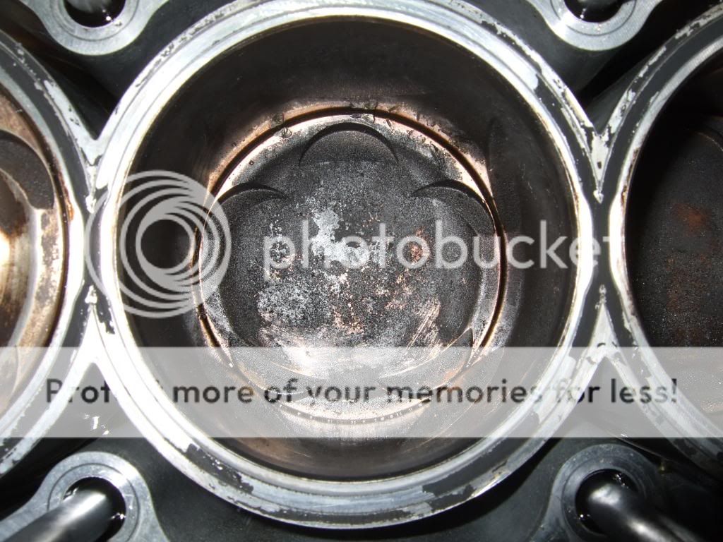
Piston #3 - Except for the carbon buildup the piston is just fine, not signs of detonation.
Piston #4 - detonation has reared it's ugly head also in #4, as you can see detonation is digging small grooves in the aluminum. Wonder if #2 and #4 piston can be used anymore. There are still no signs of deformation on the intake side of the piston.
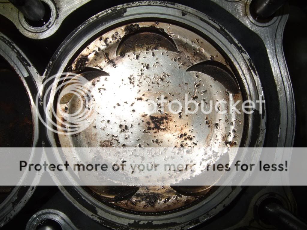
Detonation on the intake side of the piston will often deformate the intake side of the piston, with this happening the detonation will start eating away on the nicasil coating on the intake side in the cylinders cutting a groove along the edge of the piston rings. If the groove is cut deep enough it will break thru the nicasil, when that happens it will only take seconds for the detonation to break thru the cylinder block destroying it.
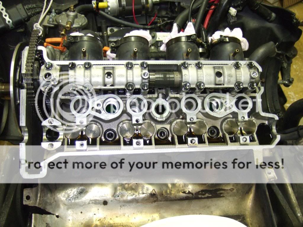
Removing valve caps and shims.
I cleaned up the cylinder head with a cotton rag to remove some of the oil. To remove the valve tappets and valve shims I used a telescopic magnet stick, the magnet is nice to use because it also holds the shim secured in the tappet until you can get a hand on it.
I started removing the intake tappets and shims. It's a good idea to make a plate to make notes at and at the same time have full controll of what parts goes where when assembling the enginge.
While removing the tappets and shims I also took notes of the shim thickness for each valve. I will use this data together with the data recorded from the valve clearance mesurements I did earlier. The measured valve clearance data determins what shim thickness I have to go with on each valve that is out of spec. I will be back with more detailed info on valve shim adjustments at a later time. Gotta order a bunch of shims I guess.
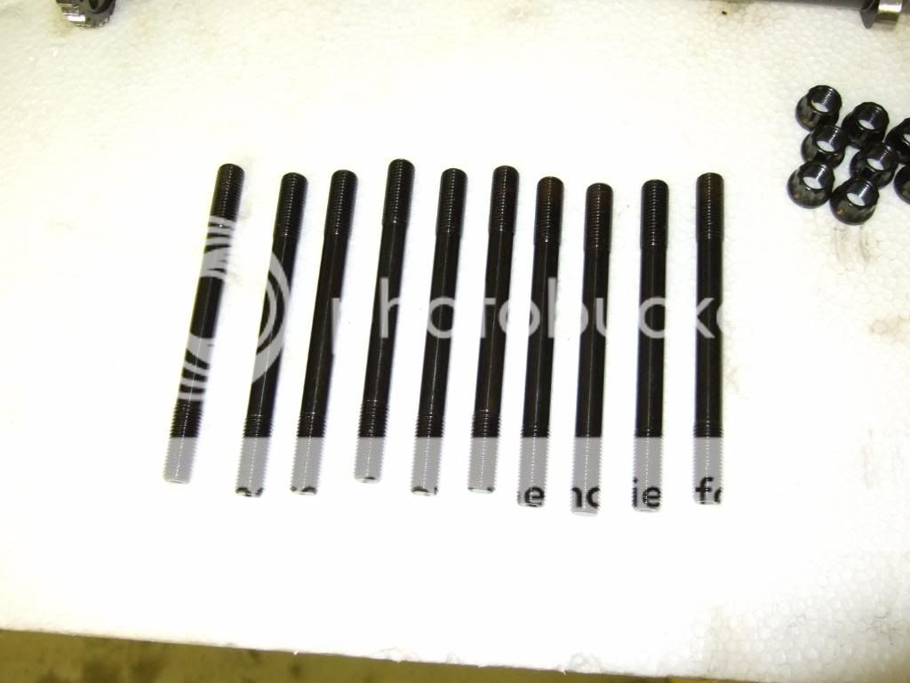
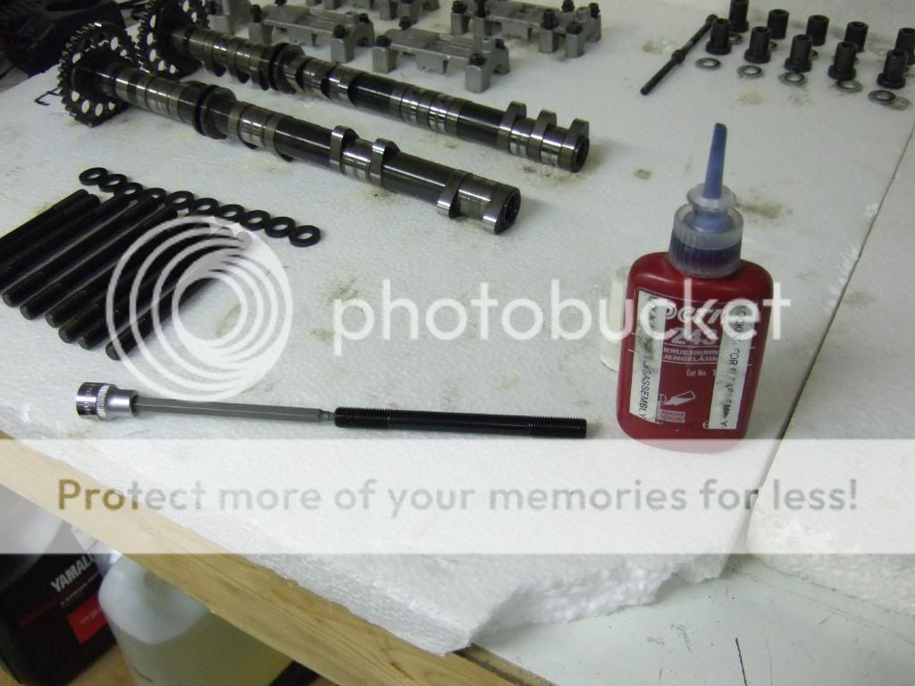
My new 10 millimeter hardened ARP head studs.
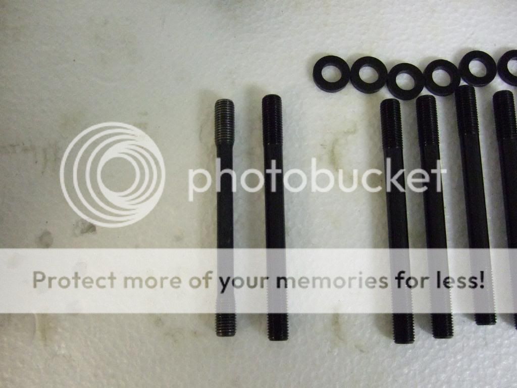
Stock cylinder head stud on the left, ARPs on the right.
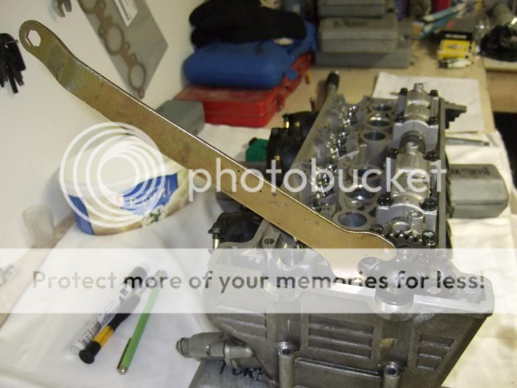
Removing stock cylinder head studs. I used two of the nuts fromt the ARP package and two 12 millimeter spanner wrenches when removing the stock studs.
Mount the first nut like shown in the pic.
Place the spanner wrench on top of the nut.

Install the second nut on top of the first spanner.

Place the second spanner on top of the nut.

Turn the lower wrench counterclockwise and the upper wrench clockwise simoultaneously, this will lock the nuts to the stud. Turn the lower wrench counterclockwise and the head stud comes loose. Remove the studs.
With the studs out of the way I removed the two hollow bushings for aligning the cylinder head and gasket to the cylinder block.
I sprayed cylinder block and head surfaces with gasket remover and let it sit for 5 minutes. I used a cotton rag and wiped the old gasket residue off the cylinder head and cylinder block.
Cleaning done.
Parts are nicely laid out on two plates on my work bench ready for valve shimming and other head work ???? LOL you know me, when in there I gotta do something, don't know exactly what yet hahahah
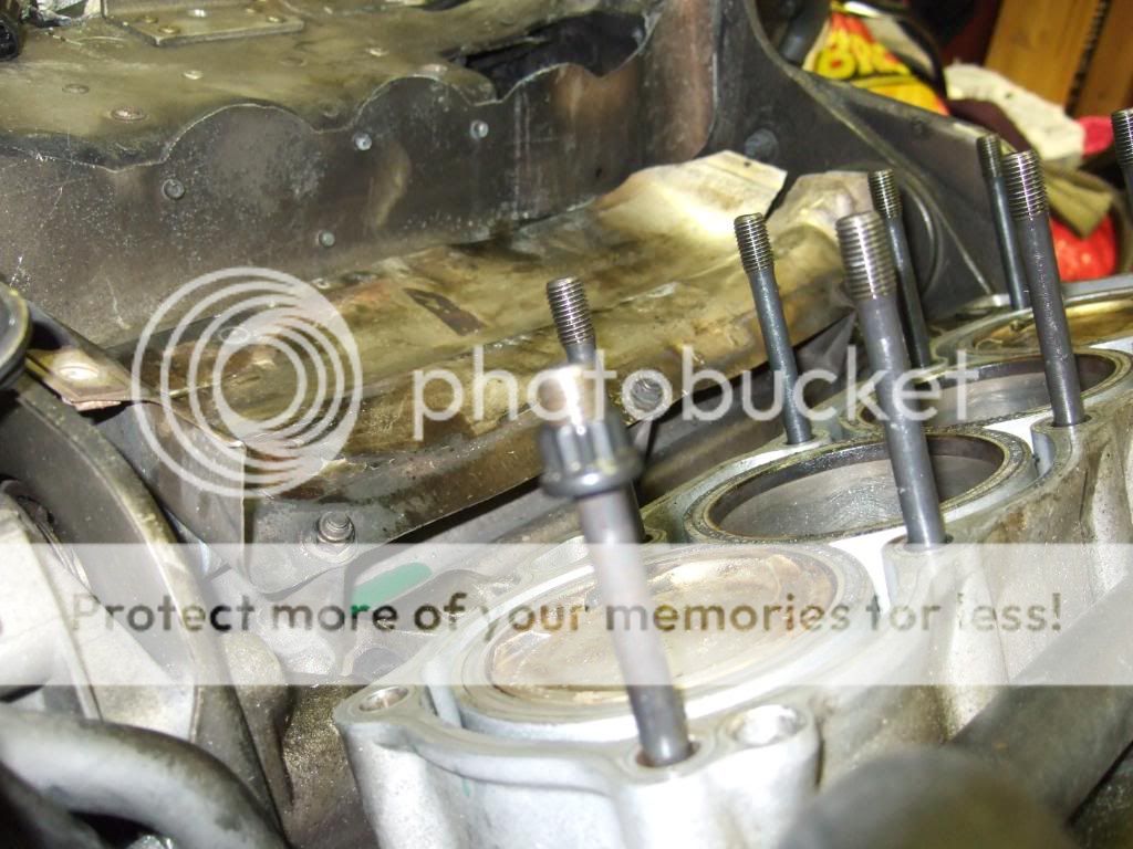
I cleaned up the threads for the 10 cylinder head stud in the block the best I could to remove oil and coolant.
I added blue Loctite to the threads going into the block and installed the bolts. ARP head studs takes a 5 millimeter Allen at the top end of the stud, this makes it real easy on the install and on removal as well.
All studs installed. I tightened them slightly with a wrench to add just a little pressure on the threads. I'm not going to install the cylinder head in a long time yet so the loctite will have time enough to harden.
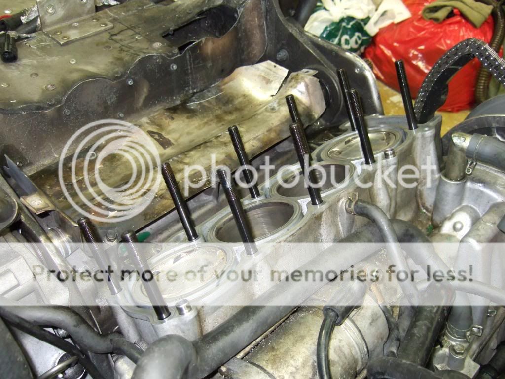
Done.
In a way I'm now past half way (if the deto do not need attention that is), I will need to have the experts take a look at the deto, if the verdict is changing of parts....well it's only a little more money and time. I have the stock pistons that I can use, need new rings and a diamond hone of the cylinders will be needed tho.....
I didn't like what I saw in there, I might pull the engine while at it hahahah here we go again, I should have done this in May I know I should ahahaha


:D")

With everything in the way removed from the sled and the valve train cover removed from the engine, I will now show you how to remove the cam shafts and so on as said in the post header. Here we go.
First step is to unwind the cam chain tensioner. This is done by removing the 10 millimeter bolt covering the cam chain tensioner release/activate mechanism. Use a medium sized flat screwdriver and turn the screw behind the 10 millimeter bolt clockwise to release pressure on the chain, make sure the screw didn't jump back to the activated setting. The cam chain tensioner have released pressure on the cam chain and you will be able to free the cams from the chain.
Next is securing the cam chain so it won't fall into the engine by accident.
Start by removing the exhaust cam. Unscrew the cam cap bolts in small increments to release the pressure from the valve springs evenly to avoid bending the cam shaft. The cam caps may stick to the cam and the cam shafts may stick to the cylinder head, to get them loose tap gently on the cam sprocket with a rubber mallet or any rubber covered tool you may have, this will make the caps and cams jump loose.
CAUTION: Tap the cam caps loose as early as possible with the bolts barely loosened. WHY? if you remove the bolts and then tap, the cam and cam caps will come flying out of the cylinder head, NOT GOOD.
The exhaust cam can be a little tricky to get loose from the cam chain. Pull the exhaust cam a little to the rear on the right end side, now you will be able to move the sprocket forward in behinde the left side of the intake cam sprocket, lift the right side of the camshaft up a little and you should be able to free the exhaust cam shaft from the chain.
It's always a good idea to lay out the cam shafts and parts on a plate excactly as they was installed in the cylinder head to avoid installing them out of order on assemby. A few of the parts are looking the same but are not the same part # so be causious that every part goes back the same place they came out from.
The routine of removing the intake cam shaft is the same as for the exhaust cam. Only difference, it's fairly easy to free it from the cam chain
CAUTION: Before loosening the cylinder head nuts make sure you have drained engine oil and coolant from the system or else you will make a flood of coolant and oil everywhere, and you will have coolant inside the crank case as well, NOT GOOD.
With the cams out of the way and the cam chain secured. I moved on to remove the cylinder head. First step is to remove the 2 #5 Allen bolts on the outside left on the cylinder head. Now to the 10 #8 Allen nuts inside the cylinderhead (one of them is actually outside the engine). Start by loosening the nuts just barely, loosen them in a star pattern starting at one of the "corners". Repeat the star pattern loosening the nuts a little of the time until the nuts are loose, remove them from the cylinder head.
To get the cylinder head loose from the cylinder block you will have to make a firm grip on the cylinder head and make a abrupt pull, this will make the cylinder head slip the gasket. If you have a friend present now is the time for him/her to help you securing the cam chain while you are lifting the cylinder head away from the engine. With the cylinder head out, secure the cam chain. Place the cylinder head on a flat and clean surface.
Here's what my combustion chambers looks like. There is some buildup of residues on the valves and combustion chamber walls. Pistons are full of tar like carbon residure that are easily wiped away by applying some gasket remover to it. There are signs of detonation in combustion chamber 2 and 4.
CC #1 - looks fine, I have been running at 11.2 AFRs at WOT last season, both the plugs, cylinder head CCs and pistons verifies the AFR readings.
CC #2 - signs of detonation down and to the right in the pic.
CC #3 - prestine exept for the residure and a slight gasket failure to the left.
CC #4 - detonation has reared it's ugly head in cylinder #4 no doubt. Our engines typically detonates at the intake side of the CC, here's the evidence.
A closer look at CC #4
Piston #1 - other than the carbon buildup the piston is prestine, no deformation or sign of detonation.
Piston #2 - signs of detonation on the edges on the intake side. Still no deformation of the piston, but I would say it has been on the edge.
Piston #3 - Except for the carbon buildup the piston is just fine, not signs of detonation.
Piston #4 - detonation has reared it's ugly head also in #4, as you can see detonation is digging small grooves in the aluminum. Wonder if #2 and #4 piston can be used anymore. There are still no signs of deformation on the intake side of the piston.
Detonation on the intake side of the piston will often deformate the intake side of the piston, with this happening the detonation will start eating away on the nicasil coating on the intake side in the cylinders cutting a groove along the edge of the piston rings. If the groove is cut deep enough it will break thru the nicasil, when that happens it will only take seconds for the detonation to break thru the cylinder block destroying it.
Removing valve caps and shims.
I cleaned up the cylinder head with a cotton rag to remove some of the oil. To remove the valve tappets and valve shims I used a telescopic magnet stick, the magnet is nice to use because it also holds the shim secured in the tappet until you can get a hand on it.
I started removing the intake tappets and shims. It's a good idea to make a plate to make notes at and at the same time have full controll of what parts goes where when assembling the enginge.
While removing the tappets and shims I also took notes of the shim thickness for each valve. I will use this data together with the data recorded from the valve clearance mesurements I did earlier. The measured valve clearance data determins what shim thickness I have to go with on each valve that is out of spec. I will be back with more detailed info on valve shim adjustments at a later time. Gotta order a bunch of shims I guess.
My new 10 millimeter hardened ARP head studs.
Stock cylinder head stud on the left, ARPs on the right.
Removing stock cylinder head studs. I used two of the nuts fromt the ARP package and two 12 millimeter spanner wrenches when removing the stock studs.
Mount the first nut like shown in the pic.
Place the spanner wrench on top of the nut.
Install the second nut on top of the first spanner.
Place the second spanner on top of the nut.
Turn the lower wrench counterclockwise and the upper wrench clockwise simoultaneously, this will lock the nuts to the stud. Turn the lower wrench counterclockwise and the head stud comes loose. Remove the studs.
With the studs out of the way I removed the two hollow bushings for aligning the cylinder head and gasket to the cylinder block.
I sprayed cylinder block and head surfaces with gasket remover and let it sit for 5 minutes. I used a cotton rag and wiped the old gasket residue off the cylinder head and cylinder block.
Cleaning done.
Parts are nicely laid out on two plates on my work bench ready for valve shimming and other head work ???? LOL you know me, when in there I gotta do something, don't know exactly what yet hahahah
I cleaned up the threads for the 10 cylinder head stud in the block the best I could to remove oil and coolant.
I added blue Loctite to the threads going into the block and installed the bolts. ARP head studs takes a 5 millimeter Allen at the top end of the stud, this makes it real easy on the install and on removal as well.
All studs installed. I tightened them slightly with a wrench to add just a little pressure on the threads. I'm not going to install the cylinder head in a long time yet so the loctite will have time enough to harden.
Done.
In a way I'm now past half way (if the deto do not need attention that is), I will need to have the experts take a look at the deto, if the verdict is changing of parts....well it's only a little more money and time. I have the stock pistons that I can use, need new rings and a diamond hone of the cylinders will be needed tho.....
I didn't like what I saw in there, I might pull the engine while at it hahahah here we go again, I should have done this in May I know I should ahahaha
Buddy - sorry to see that you had detonation. Any idea what caused it - glooged jet? You ran good AFR with meth.
Hope you get here done before snow starts to fly!
The ARP studs look longer than stock studs - do you have to cut them to OEM length before installing them?
Hope you get here done before snow starts to fly!
The ARP studs look longer than stock studs - do you have to cut them to OEM length before installing them?
rxrider
Jan-Ove Pedersen
- Joined
- Apr 25, 2003
- Messages
- 7,355
- Age
- 60
- Location
- Lakselv - 70N & 25E
- Country
- Norway
- Snowmobile
- 2014 Phazer XTX, 2013 Phazer RTX, 2008 Apex RTX, 2007 Warrior, 2006 Attak
Would you think I have to replace any parts, don't look like it but I may have to. Well i could have gone deto when off meth, ran it a lot that way last year, remember I had problems running on meth with 11+ AFRs at wot. Problem is I havn't had the engine open since the first season when I blew the head gaskets out.... so I really don't know when this happened, it may have happened every once and while over the last 3 years.
I will, you bet buddy, I even quit work to get her done hahahaha.
No need to cut down the studs they are only slightly longer and there's enough room, no problem.
I will, you bet buddy, I even quit work to get her done hahahaha.
No need to cut down the studs
they are only slightly longer and there's enough room, no problem.rxrider
Jan-Ove Pedersen
- Joined
- Apr 25, 2003
- Messages
- 7,355
- Age
- 60
- Location
- Lakselv - 70N & 25E
- Country
- Norway
- Snowmobile
- 2014 Phazer XTX, 2013 Phazer RTX, 2008 Apex RTX, 2007 Warrior, 2006 Attak
I have studied the last set of spark plugs, no signs of aluminum particles. I have kept a several of the plug sets I've ran in my turbo, one of the sets from 2-3 years back shows signs of aluminum, my guess is that deto happened a few years ago.
rxrider
Jan-Ove Pedersen
- Joined
- Apr 25, 2003
- Messages
- 7,355
- Age
- 60
- Location
- Lakselv - 70N & 25E
- Country
- Norway
- Snowmobile
- 2014 Phazer XTX, 2013 Phazer RTX, 2008 Apex RTX, 2007 Warrior, 2006 Attak
Update September 22. - Reinstalling intake cam shaft to check valve clearance.
My feeler gauge is metric in 0.05 millimeter increments, not accurate enough to measure the intake cam valve clearance. Yesterday I ordered a the original Yamaha valve clearance measuring tool found in the RX-1 Technical Update Book. The tool will arrive at my dealer in a few days time, going to redo the measuring for the intake cam before ordering the valve shims needed to get all valve clearances to the high end of spec.
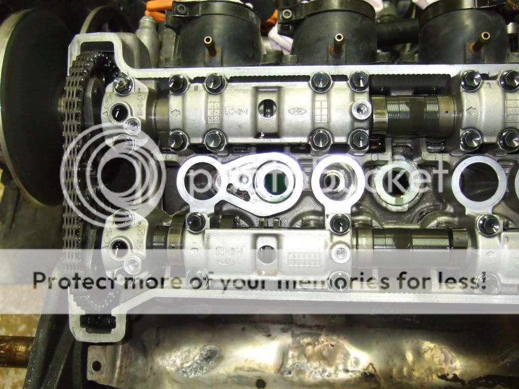
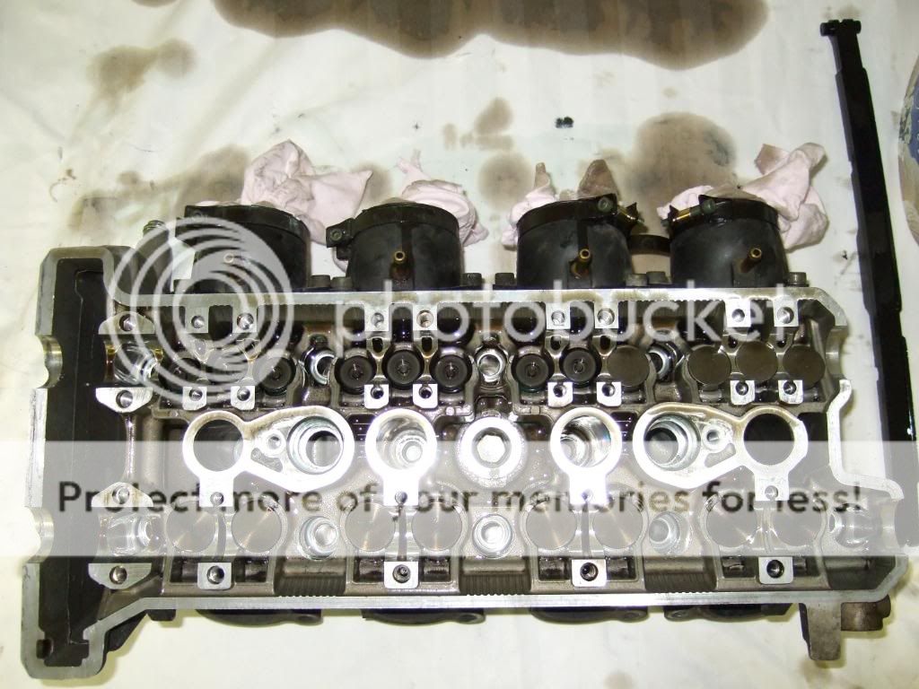
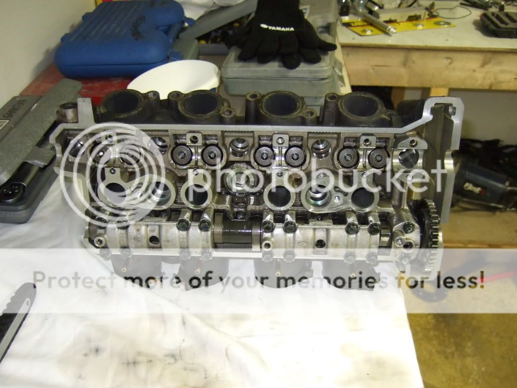
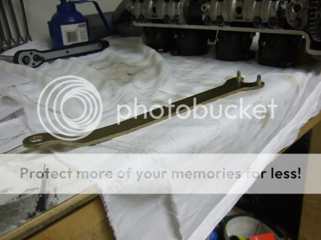
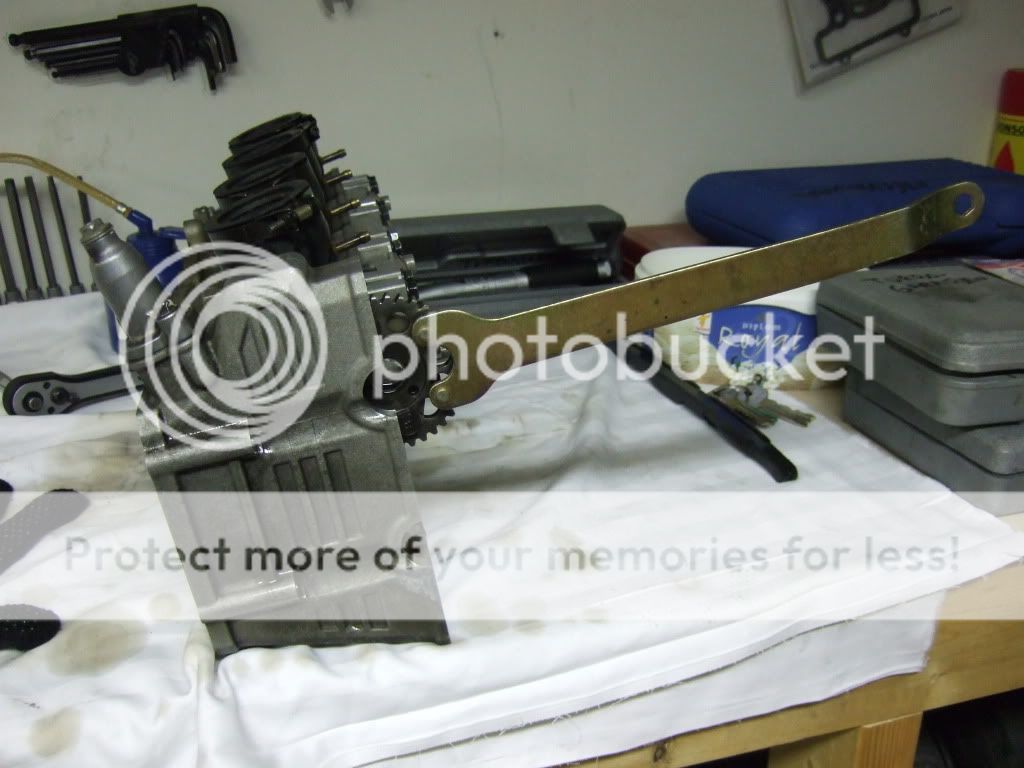
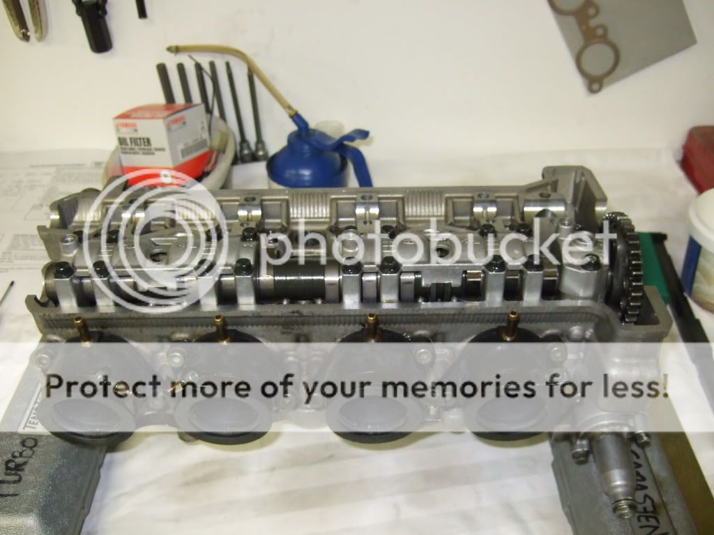
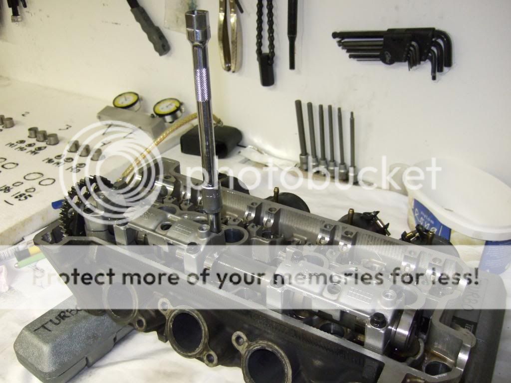
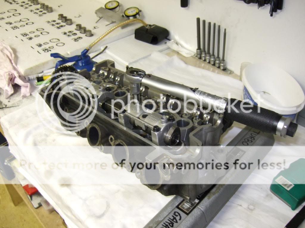
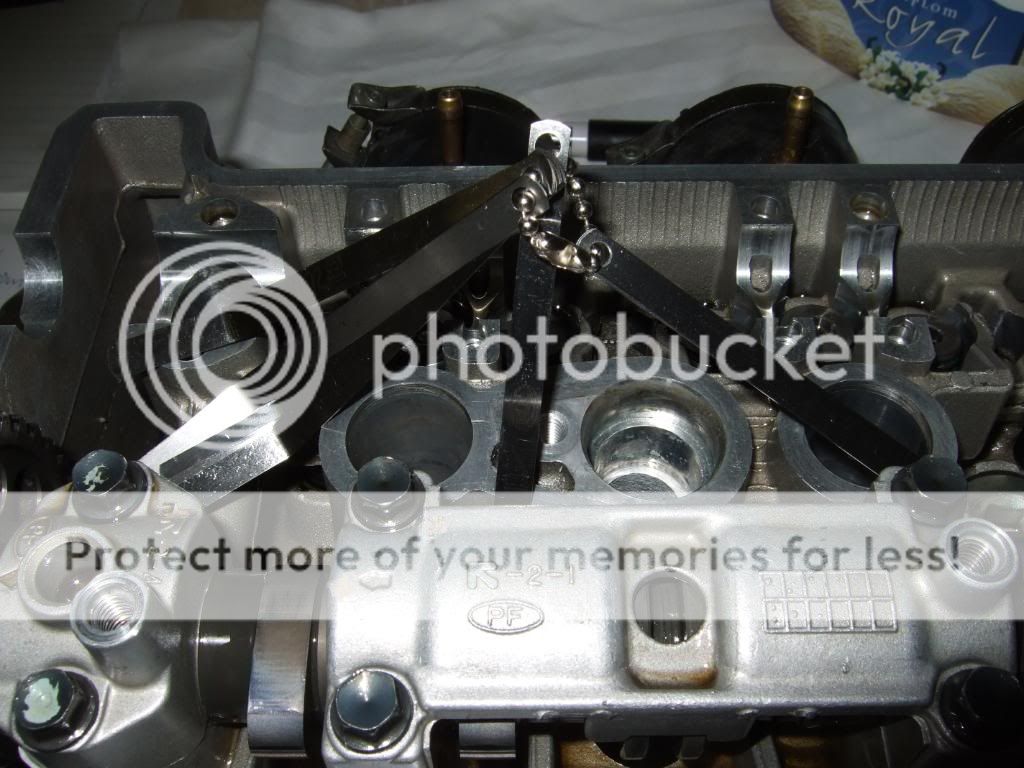
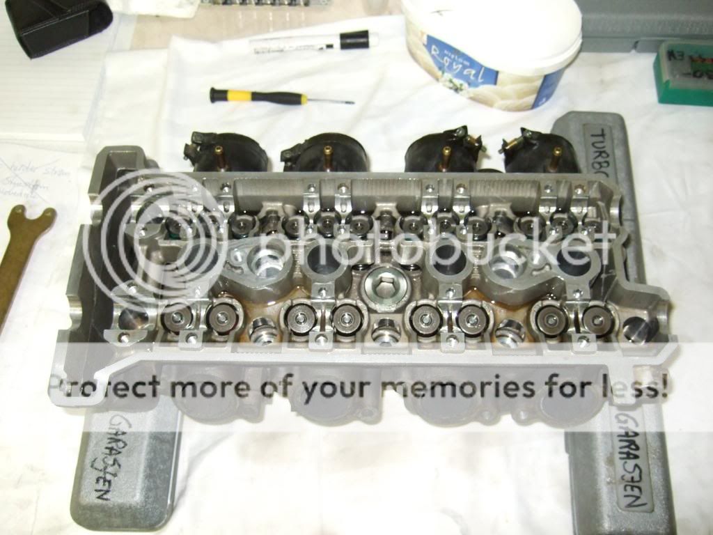
I reinstalled the intake cam, ready for checking valve clearances with the proper tool.
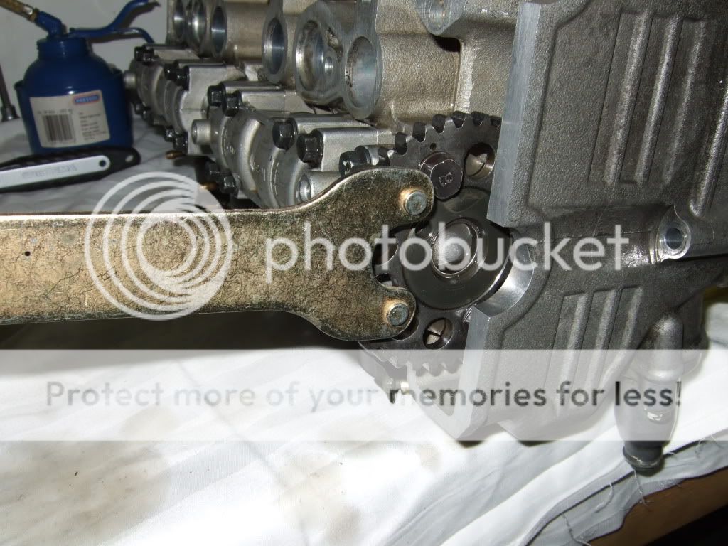
To be able to turn the cam shaft I used the blade install tool from my largest die grinder, 9"-10" or 22cm-25cm blade. Great tool for turning the cam shaft. The tool fits nicely into every other hole in the cam gear and makes it very easy to turn the cam shaft.
After reinstallling the intake cam shaft I turned the cam for several revolutions to make sure all valve shims and valve buckets were seated properly.
All is set and ready, all I need is the new feeler blades.

My feeler gauge is metric in 0.05 millimeter increments, not accurate enough to measure the intake cam valve clearance. Yesterday I ordered a the original Yamaha valve clearance measuring tool found in the RX-1 Technical Update Book. The tool will arrive at my dealer in a few days time, going to redo the measuring for the intake cam before ordering the valve shims needed to get all valve clearances to the high end of spec.
I reinstalled the intake cam, ready for checking valve clearances with the proper tool.
To be able to turn the cam shaft I used the blade install tool from my largest die grinder, 9"-10" or 22cm-25cm blade. Great tool for turning the cam shaft. The tool fits nicely into every other hole in the cam gear and makes it very easy to turn the cam shaft.
After reinstallling the intake cam shaft I turned the cam for several revolutions to make sure all valve shims and valve buckets were seated properly.
All is set and ready, all I need is the new feeler blades.
rxrider said:I have studied the last set of spark plugs, no signs of aluminum particles. I have kept a several of the plug sets I've ran in my turbo, one of the sets from 2-3 years back shows signs of aluminum, my guess is that deto happened a few years ago.
First off - you didn't deserve this

But it is good that you figured out what happend - hang in there buddy and get her fixed before snow starts to fly
No more tuning in late May - LOLPull that engine and get her looked over - meassure the cylinder shape and make sure alle bearings/rods are in good condition. It will give you pice of mind during the winter
!")
rxrider
Jan-Ove Pedersen
- Joined
- Apr 25, 2003
- Messages
- 7,355
- Age
- 60
- Location
- Lakselv - 70N & 25E
- Country
- Norway
- Snowmobile
- 2014 Phazer XTX, 2013 Phazer RTX, 2008 Apex RTX, 2007 Warrior, 2006 Attak
Hahahaha I'm in deep, problems like this are to be expected when playing with fire (high boost).
After carefully studying the spark plugs I ran 2-3 years ago I know deto happend way back, plugs from back then told the story last night, they have microscopic aluminum particles on them, the plugs I ran last season does not have any.
I will pull the engine today, gotta do that anyhow to be able to degree the cams, my degree wheel are hugh as a large pizza LOL
rxrider
Jan-Ove Pedersen
- Joined
- Apr 25, 2003
- Messages
- 7,355
- Age
- 60
- Location
- Lakselv - 70N & 25E
- Country
- Norway
- Snowmobile
- 2014 Phazer XTX, 2013 Phazer RTX, 2008 Apex RTX, 2007 Warrior, 2006 Attak
Update September 28. - Preparing to check valve clearance.
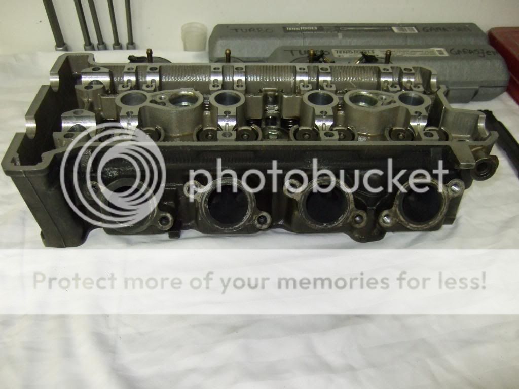
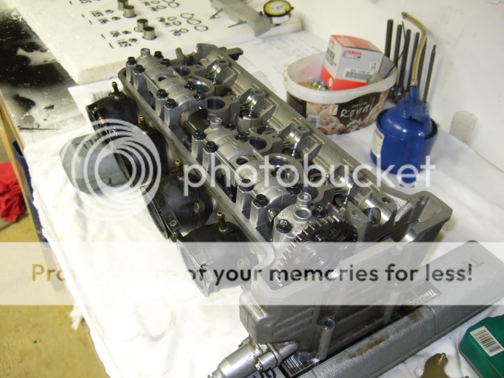
I have prepared the head for valve clearance measuring and adjustment as soon as I get the valve clearance feeler gauge tool I ordered from Yamaha. I used my two TengTools Tork wrench boxes to rig my cylinder head upon, now I can turn the cams without having the valves hitting anything.
I have reinstalled the intake valve buckets and shims, then reinstalled the intake cam to make measurements with the Yamaha tool.... when I get it that is.
I have been in contact with Greg Santry at PowerByGNS.com with questions on what lobe center degrees to go with. I will be back with the exact intake and exhaust specs for both RX-1 and Apexwhen I have the cam lobe centers set.
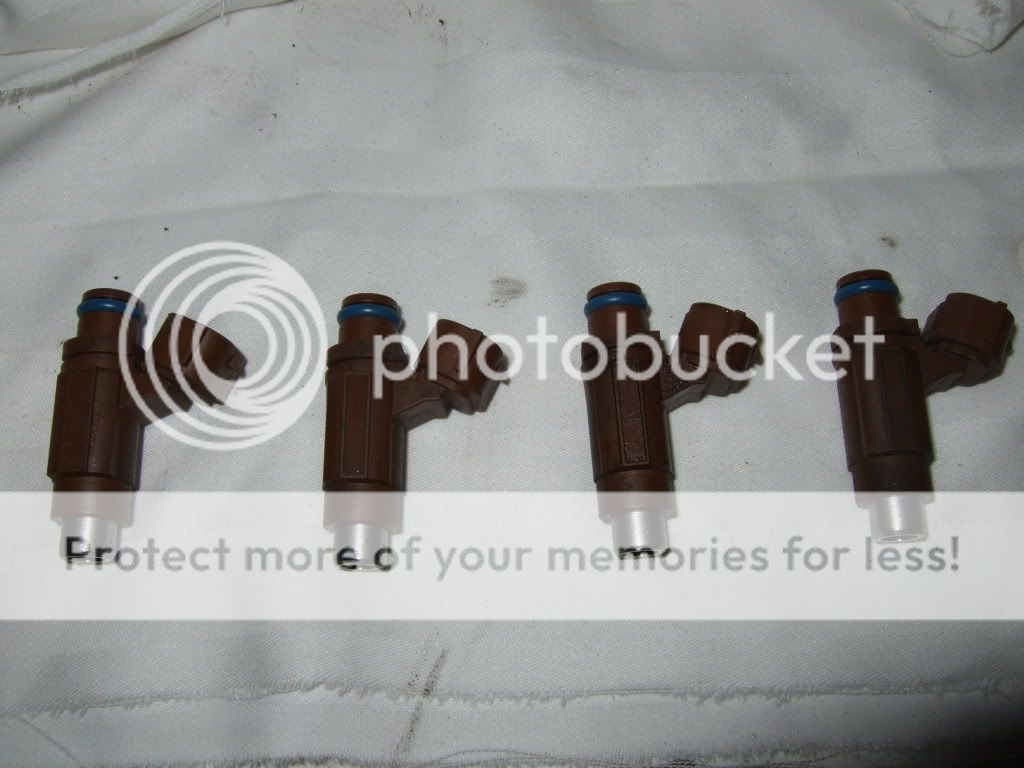
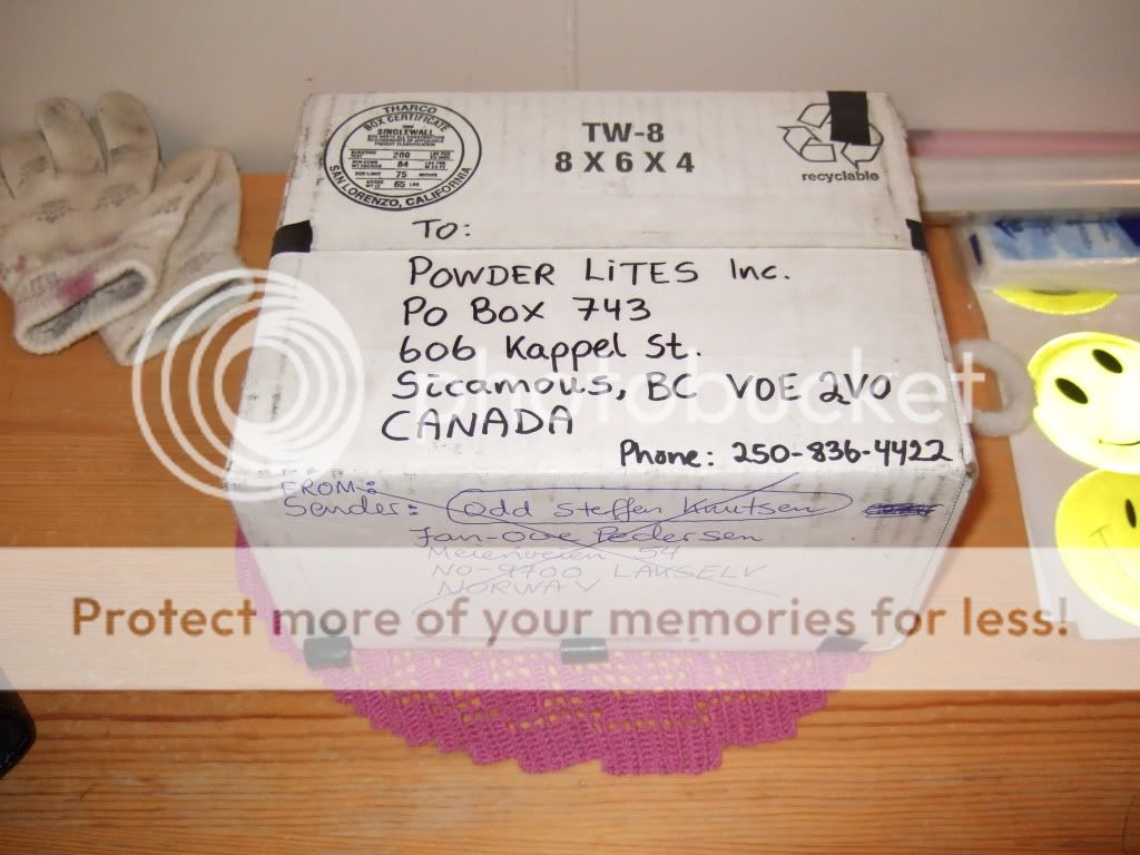
My friend Odd Steffen is going with larger injectors when going from MCX IC to Powder Lites IC, the PL IC does not have extra injectors so the stock injectors are going to high capasity injectors, will be back with exact fuel feed #s when we have the new injectors in house. I have volunteered to work on his sled while he is away Moose hunting, I removed the injector parts. Here's a pic of the stock injectors ready to ship.
Not funny sitting around waiting for tools, all depends on setting the valve lash or valve clearance before degreeing the cams. Installing the head with higher compression, and all other stuff that needs to be done.... and wither is closing in hahahaha no need to get frightened not to get her done in time at this time.....
I don't like sitting around doing nothing so I'm glad my friend need some help with his sled while he's away Thanks buddy, it helps me keep my sanity not beeing able to work on my sled LOL.
I have prepared the head for valve clearance measuring and adjustment as soon as I get the valve clearance feeler gauge tool I ordered from Yamaha. I used my two TengTools Tork wrench boxes to rig my cylinder head upon, now I can turn the cams without having the valves hitting anything.
I have reinstalled the intake valve buckets and shims, then reinstalled the intake cam to make measurements with the Yamaha tool.... when I get it that is.
I have been in contact with Greg Santry at PowerByGNS.com with questions on what lobe center degrees to go with. I will be back with the exact intake and exhaust specs for both RX-1 and Apexwhen I have the cam lobe centers set.
My friend Odd Steffen is going with larger injectors when going from MCX IC to Powder Lites IC, the PL IC does not have extra injectors so the stock injectors are going to high capasity injectors, will be back with exact fuel feed #s when we have the new injectors in house. I have volunteered to work on his sled while he is away Moose hunting, I removed the injector parts. Here's a pic of the stock injectors ready to ship.
Not funny sitting around waiting for tools, all depends on setting the valve lash or valve clearance before degreeing the cams. Installing the head with higher compression, and all other stuff that needs to be done.... and wither is closing in hahahaha no need to get frightened not to get her done in time at this time.....
I don't like sitting around doing nothing so I'm glad my friend need some help with his sled while he's away
Thanks buddy, it helps me keep my sanity not beeing able to work on my sled LOL.

Looks good rx I will send my sled over and have you finish it for me FOR FREE of course. LOL
rxrider
Jan-Ove Pedersen
- Joined
- Apr 25, 2003
- Messages
- 7,355
- Age
- 60
- Location
- Lakselv - 70N & 25E
- Country
- Norway
- Snowmobile
- 2014 Phazer XTX, 2013 Phazer RTX, 2008 Apex RTX, 2007 Warrior, 2006 Attak
I'll do the work for free but I'll keep your sled LOL
rxrider
Jan-Ove Pedersen
- Joined
- Apr 25, 2003
- Messages
- 7,355
- Age
- 60
- Location
- Lakselv - 70N & 25E
- Country
- Norway
- Snowmobile
- 2014 Phazer XTX, 2013 Phazer RTX, 2008 Apex RTX, 2007 Warrior, 2006 Attak
Update September 29. - Checking valve clearance.
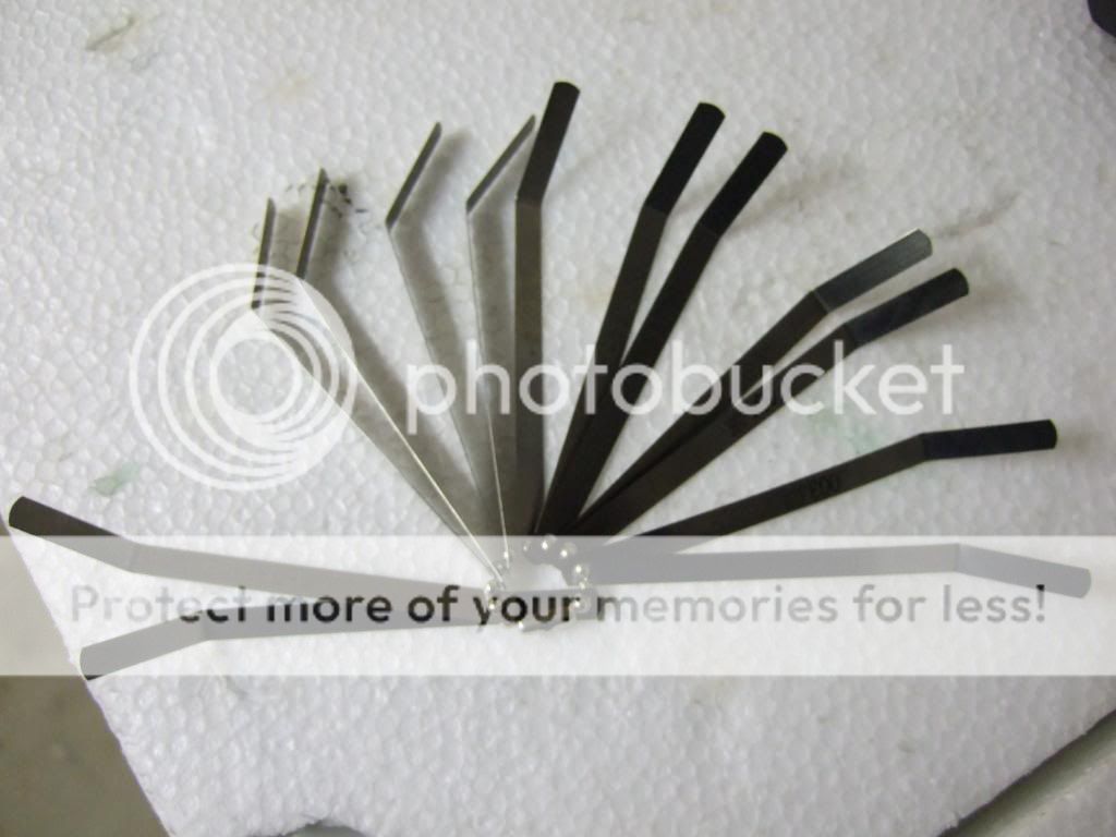
I finally got my Yamaha Valve Clearance Feeler Blade Tool
It goes in steps like follows:
Inch Metric millimeter
0.002 = 0.051
0.003 = 0.076
0.004 = 0.102
0.005 = 0.127
0.006 = 0.152
0.007 = 0.177
0.008 = 0.203
0.009 = 0.228
0.010 = 0.254
0.011 = 0.279
0.012 = 0.304
0.013 = 0.330
0.014 = 0.356
Here's a few pics of the tool.
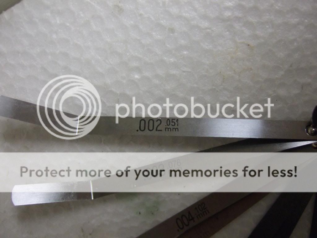


The whole works
Measuring, the procedure:
- If you have the cylinder head on the workbench this is the way I prefer to measure the valve clearance. Can be done with the cylinder head on the engine as well.
- Install valve shims and bucket (assuming all valve shims and buckets are removed from the cylinder head).
- Install the exhaust cam to the cylinder head and tighten down the cam caps to spec.
- Rotate the cam shaft clockwise (seen from the right hand side of the cylinder head) 4-5 revolutions to seat the valve shim and bucket.
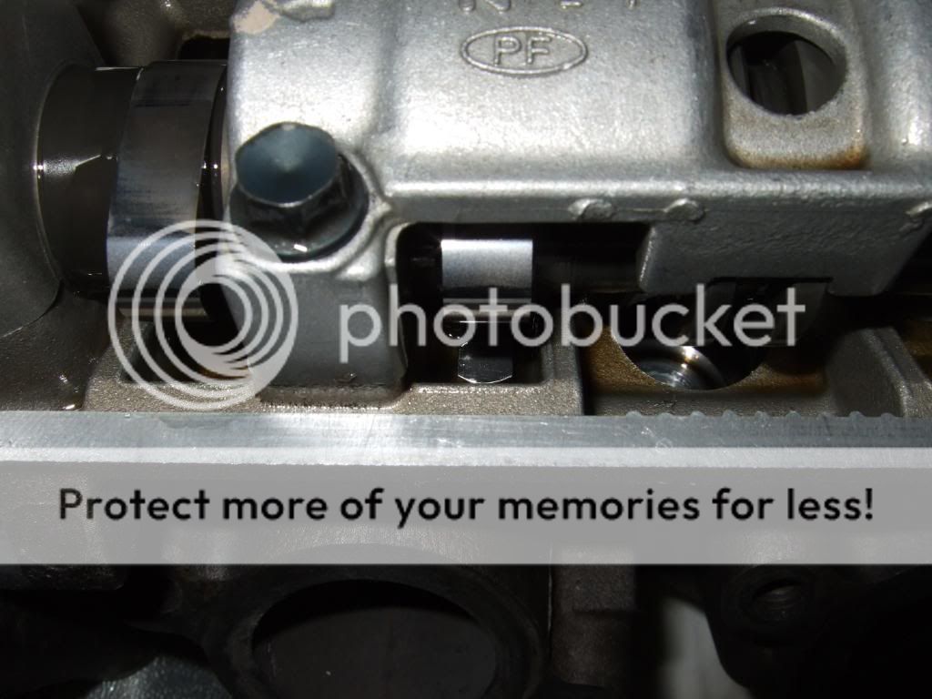
- Rotate the camshaft until cylinder #1 has all valves closed, the lobe is now pointing away from the intake cam (if installed).
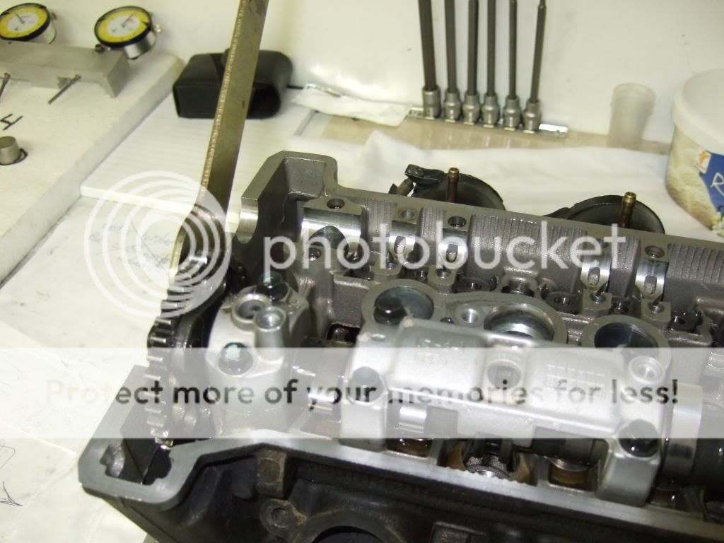
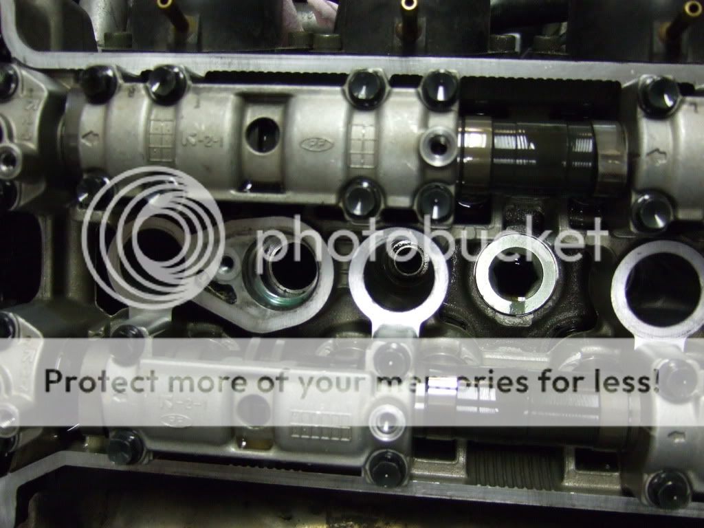
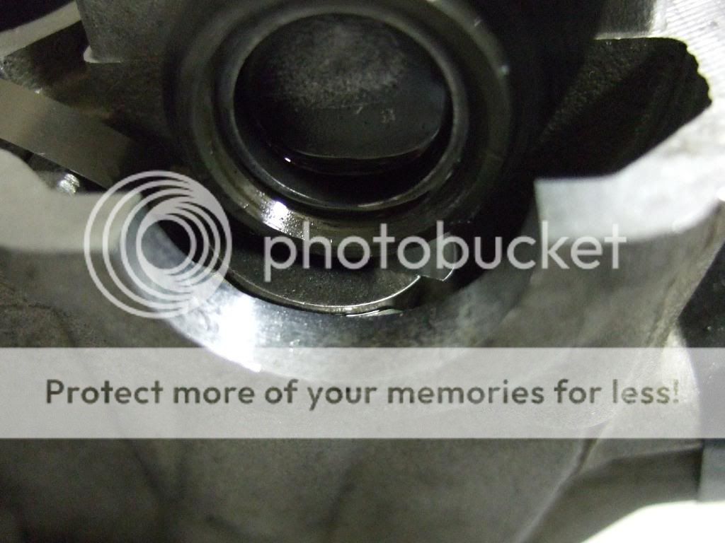
- Insert the feeler blade from the inside of the cylinder head and out like shown in the pics below.
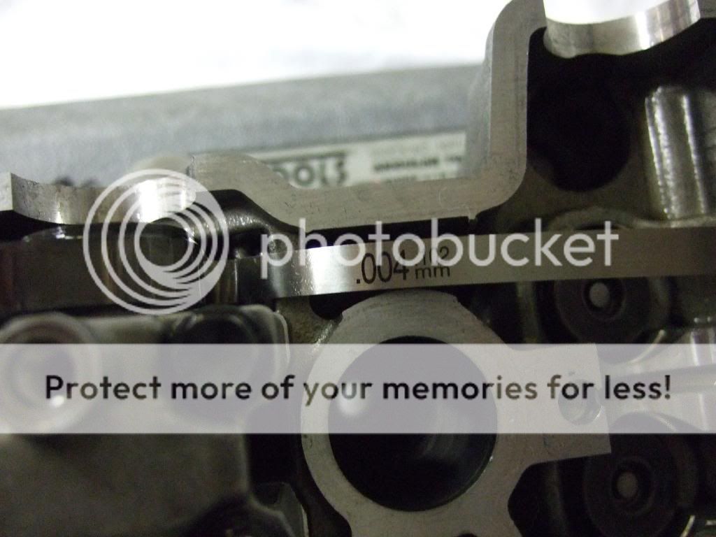
- If the feeler blade fits in between the valve bucket and cam go up one size until the next blade won't fit go back down one and write down the #s.
- If the feeler blade dows not fit, go down one size at the time until it fits, write down the #s.
- Rotate the cam until cylinder 2 has all valves closes ......... and repeate the steps until done.
- Remove the exhaust cam, install the instake cam ..... repeat the steps above until done.
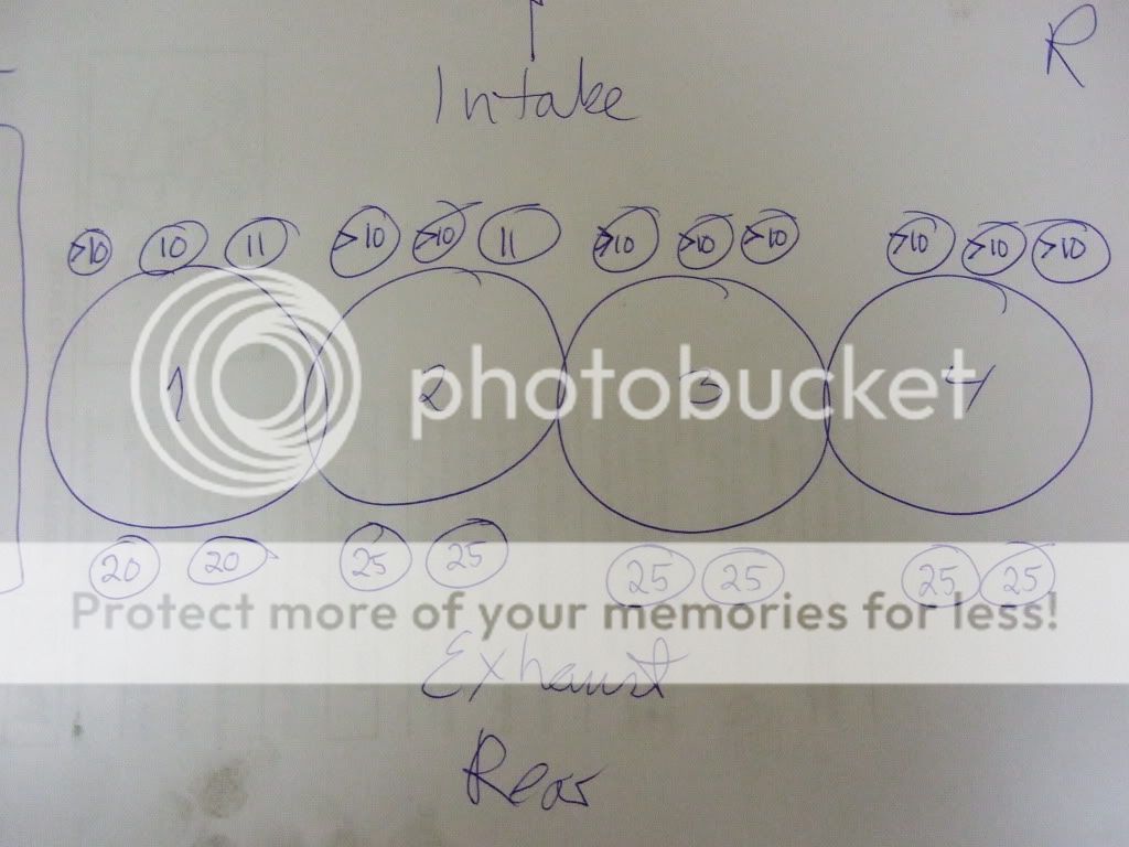
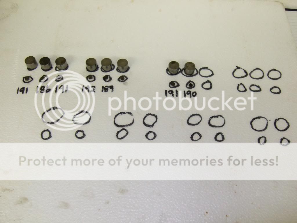
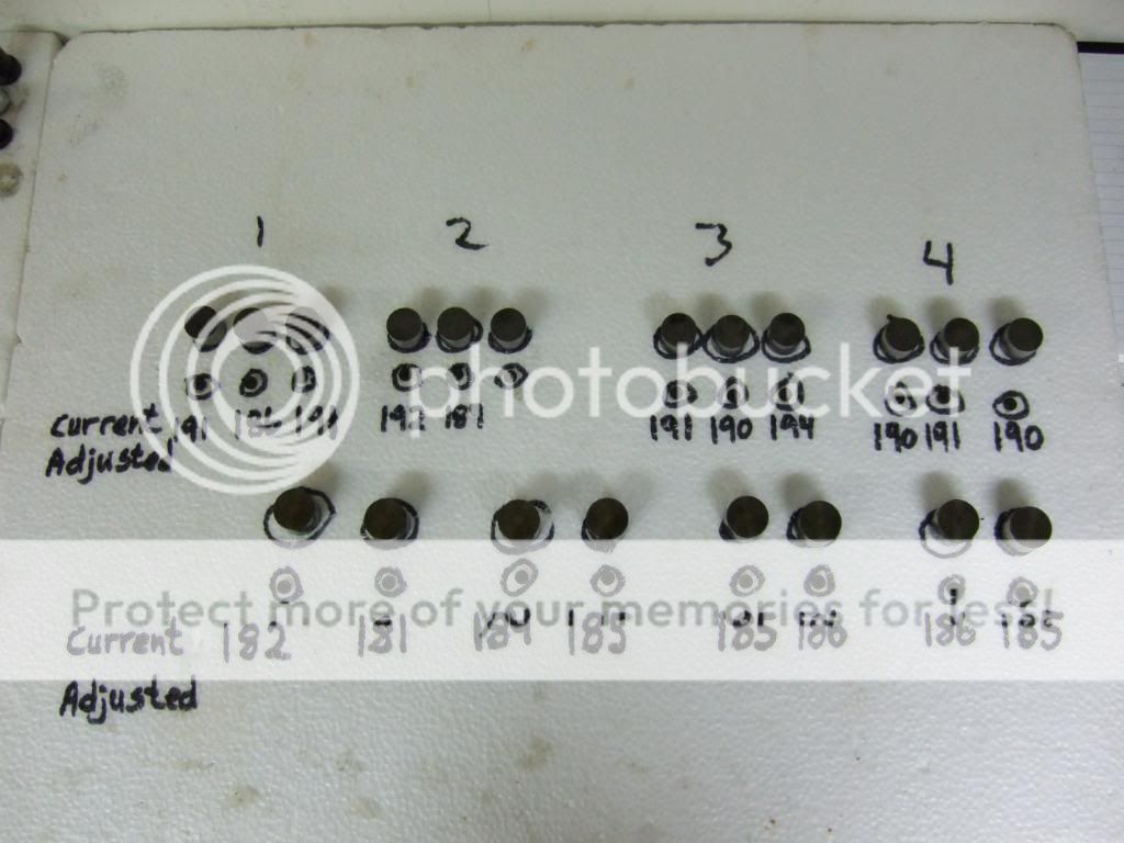
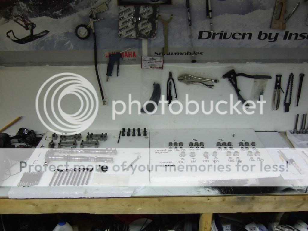
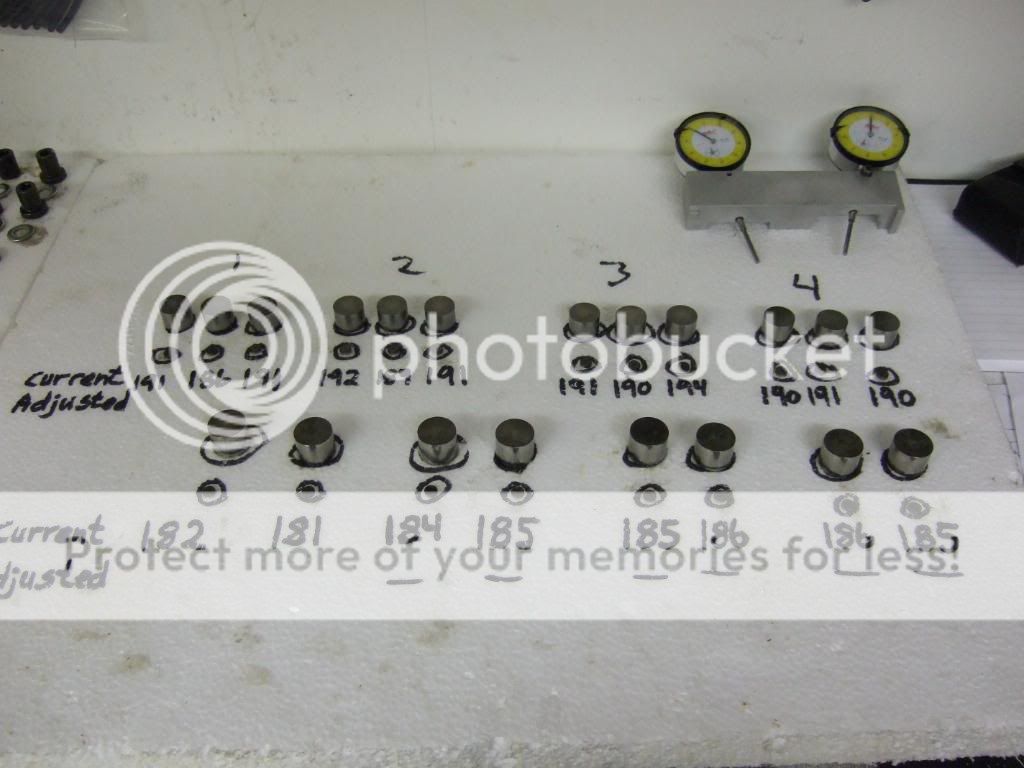
You will now have a list like the one shown below. You write down the #s anyway you want, this is how I prefer to do it. Sorry about my drawings, my kids are way better than me when it comes to drawing LOL
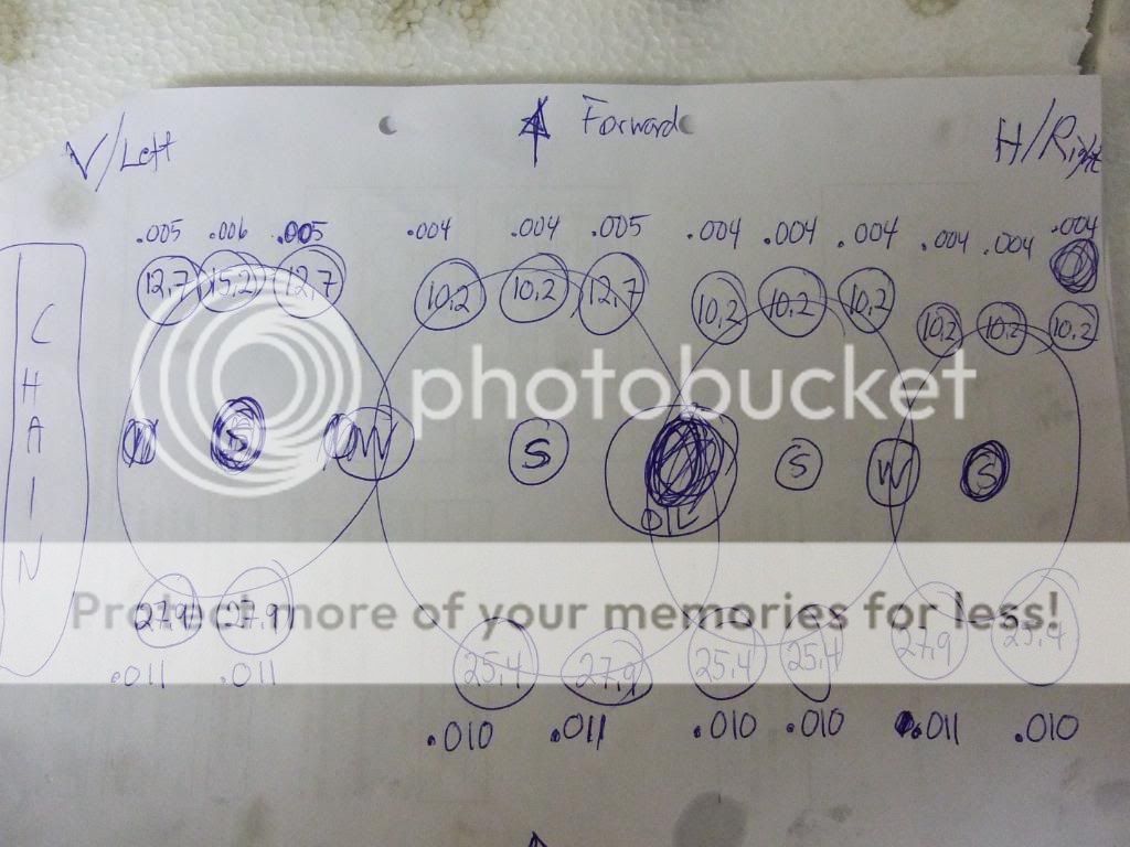
The measurements done is used to determine what shim thickness to install on every valve that is measured to be out of spec.
I have enclosed a spreadsheet posted by another member on TY (sorry it's so long ago I can't remember to give credit to, I will if I ever find out). I did
I found it in a post by TY member lakercr - http://www.ty4stroke.com/viewtopic.php? ... c826b802cf
In the spreadsheet you record the shim#s for every valve and the valve clearance measured. The spread sheet will calculate the shim dimension needed. I will not go in detail on how the spreadsheet works, but I will answere questions and post the answeres here for reference.
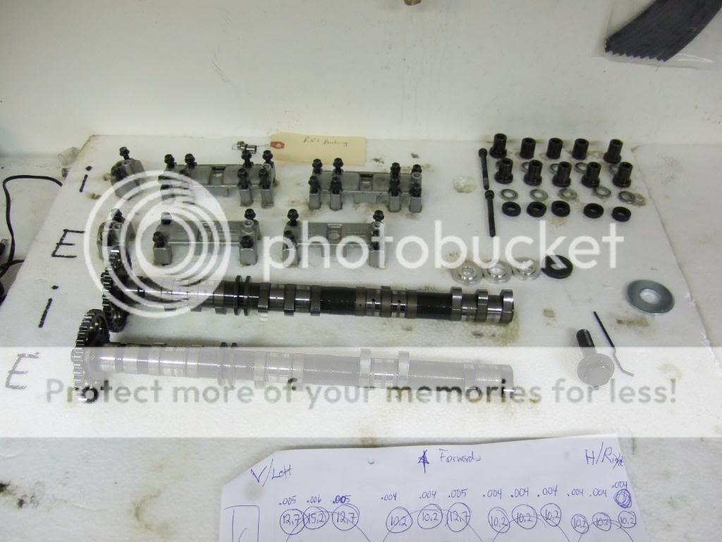
When done measuring I removed the cams, buckets and valve shims to prepare for valve shim adjustment.
Before calling it a day I cleaned up a little on the workbench. I have layed out all shims and cylinder head parts on plates to keep it neat and tidy I like it this way when working.
Later in the evening I calculated which valves needs adjustment. The valves that needs replacement can be reused in another position so I ended up ordering 9 new valves in total. Most valves are out of spec or too close to the lower #s of spec. In a boosted application you want valve clearance to be close to the higher #s of spec.
I would like to say a thank you to lakercr for providing the valve adjustment spreadsheet. I have made a few modifications to it to add some functionality, that's all. Thanks lakercr


I finally got my Yamaha Valve Clearance Feeler Blade Tool
It goes in steps like follows:
Inch Metric millimeter
0.002 = 0.051
0.003 = 0.076
0.004 = 0.102
0.005 = 0.127
0.006 = 0.152
0.007 = 0.177
0.008 = 0.203
0.009 = 0.228
0.010 = 0.254
0.011 = 0.279
0.012 = 0.304
0.013 = 0.330
0.014 = 0.356
Here's a few pics of the tool.
The whole works
Measuring, the procedure:
- If you have the cylinder head on the workbench this is the way I prefer to measure the valve clearance. Can be done with the cylinder head on the engine as well.
- Install valve shims and bucket (assuming all valve shims and buckets are removed from the cylinder head).
- Install the exhaust cam to the cylinder head and tighten down the cam caps to spec.
- Rotate the cam shaft clockwise (seen from the right hand side of the cylinder head) 4-5 revolutions to seat the valve shim and bucket.
- Rotate the camshaft until cylinder #1 has all valves closed, the lobe is now pointing away from the intake cam (if installed).
- Insert the feeler blade from the inside of the cylinder head and out like shown in the pics below.
- If the feeler blade fits in between the valve bucket and cam go up one size until the next blade won't fit go back down one and write down the #s.
- If the feeler blade dows not fit, go down one size at the time until it fits, write down the #s.
- Rotate the cam until cylinder 2 has all valves closes ......... and repeate the steps until done.
- Remove the exhaust cam, install the instake cam ..... repeat the steps above until done.
You will now have a list like the one shown below. You write down the #s anyway you want, this is how I prefer to do it. Sorry about my drawings, my kids are way better than me when it comes to drawing LOL
The measurements done is used to determine what shim thickness to install on every valve that is measured to be out of spec.
I have enclosed a spreadsheet posted by another member on TY (sorry it's so long ago I can't remember to give credit to, I will if I ever find out). I did
I found it in a post by TY member lakercr - http://www.ty4stroke.com/viewtopic.php? ... c826b802cf
In the spreadsheet you record the shim#s for every valve and the valve clearance measured. The spread sheet will calculate the shim dimension needed. I will not go in detail on how the spreadsheet works, but I will answere questions and post the answeres here for reference.
When done measuring I removed the cams, buckets and valve shims to prepare for valve shim adjustment.
Before calling it a day I cleaned up a little on the workbench. I have layed out all shims and cylinder head parts on plates to keep it neat and tidy
I like it this way when working.
Later in the evening I calculated which valves needs adjustment. The valves that needs replacement can be reused in another position so I ended up ordering 9 new valves in total. Most valves are out of spec or too close to the lower #s of spec. In a boosted application you want valve clearance to be close to the higher #s of spec.
I would like to say a thank you to lakercr for providing the valve adjustment spreadsheet. I have made a few modifications to it to add some functionality, that's all. Thanks lakercr
Attachments
Similar threads
- Replies
- 46
- Views
- 149K
-
This site uses cookies to help personalise content, tailor your experience and to keep you logged in if you register.
By continuing to use this site, you are consenting to our use of cookies.