Ruckus
TY 4 Stroke Master
phazerdrew
Extreme
just installed my bushings... much better than b4 still slop there but I dont think whats left can be fixed... just too many linkages in the steering. BUSHMAN how tight do you have the bolts where the bushings are.. i put them to about how tight they were from the factory, but the steering block was locked up.. backed off 1/4 turn and everything is good
Hey phazerdrew I backed mine off a touch and there were good a little snug. The Collar on the stock Bushings are a bit longer so when torqued tight they still moved quite freely. Any slop that is left in the Steering System is in the ball joints thanks again.
phazerdrew
Extreme
thanks bushman.. the whole front end of my sled is beat, i have the ulmer kit for the A arms installing tomorrow, dealer is replacing upper and lower ball joints under warranty. Hopefully that solves most of the slop
JohnnyHollywood
Extreme
Thanks bushman... got 'em yesterday. 

Ricketts
Pro
Got em installed today...real PITA. Had some choice words for the Yamaha engineers...  Definitely worth pulling the entire linkage to work on it on the bench. I figured instead of trying to press out the tie rod ends I pulled the tie rods off the skiis and spun them out of the end of the steering linkage.
Possibly even easier if I would have pulled the entire front sub frame off as per Cannondale's oil change trick.
Front end seems a fair bit tighter. Thanks Upbushman!!
Rick
 Definitely worth pulling the entire linkage to work on it on the bench. I figured instead of trying to press out the tie rod ends I pulled the tie rods off the skiis and spun them out of the end of the steering linkage.
 Possibly even easier if I would have pulled the entire front sub frame off as per Cannondale's oil change trick.
Front end seems a fair bit tighter. Thanks Upbushman!!
Rick
Hey Ricketts I found that leaving the nuts on the Ball Joints at the Idler Arm and using a long 1/2" extension and wacking them twice or so does the trick. Having worked enough on this sled to get familiar with what works on the engineering hemroid for us guys just takes time thanks again on feedback.
Ricketts
Pro
I remember you saying that but I figured I would have just as much trouble trying to get the tie rod ends back in 
Spinning off the tie rods worked not too bad...I have to check my alignment anyways!!
Just need some snow...
Rick

Spinning off the tie rods worked not too bad...I have to check my alignment anyways!!
Just need some snow...
Rick
Jeremy
Expert
Stupid question but I seem to be haveing a blonde moment. Which is recomended, toe in or toe out ???


karl
Lifetime Member
- Joined
- Dec 9, 2007
- Messages
- 228
- Location
- Whitehorse, Yukon Territory
- Country
- Canada
- Snowmobile
- 2015 Phazer XTX
toe out - manual states 0 - 15mm (0 - .59 in)
Hey guys it is also easier to leave the Pivot Assembly loose in the chassis without bolts holding it in place. Then put the Tie Rod Ends in the Idler Arm with hole for saftey pin vertical and then put the nuts on, also more room for the fingers to operate. Tighten the nuts tight on the Tie Rods after you tighten the Pivot Assembely.
I have pulled this thing apart enough times through Bushing Kit design it becomes alot easier than maybe for others doing it. I will give an exact tear down and reassembly after Thanksgiving have an awesome dinner thanks again.
I have pulled this thing apart enough times through Bushing Kit design it becomes alot easier than maybe for others doing it. I will give an exact tear down and reassembly after Thanksgiving have an awesome dinner thanks again.
Jeremy
Expert
Looking forwards to your 1 2 3 teardown procedure.
Prav
Pro
- UP bushman -
Great kit... but you can mark that down as something that wouldn't hurt my feelings if I never had to do it again!
Great kit... but you can mark that down as something that wouldn't hurt my feelings if I never had to do it again!
Thankfully that will be it unless something breaks and needs replacement  . You know the Engineering Department does not wrench on this stuff and if they do it is already disassembled by someone else thanks for the feedback.
 . You know the Engineering Department does not wrench on this stuff and if they do it is already disassembled by someone else thanks for the feedback.
Instructions For Disassembly To Replace Bushing Kit
From my viewpoint this instruction is the easiest way to replace the Bushing Kit for Pivot, Idler Arm Assembly. During the design of the Bushing Kit and testing this assembly has been removed from the sled 6 times. So this has become pretty easy from my view about 1 hour to complete.
HEADLIGHT COVER DIAGRAM 1 & 3:
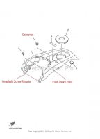
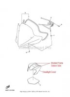
Remove the HEADLIGHT COVER #1 DIAGRAM 1 which has two molded points on it that push through the rubber grommets #3 DIAGRAM 3 on the FUEL TANK COVER. You can put your fingers underneath by the steering column to press up on the molded points when removing HEADLIGHT COVER (be careful if it is really cold they might break I found this out the hard way).
HEADLIGHT DIAGRAM 2 & 3:
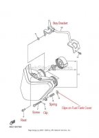
Disconnect the 2 headlight bulb plugs from the back of the HEADLIGHT. Remove the 2 phillips screws #7, springs #8 and clips #6 DIAGRAM 2 at the bottom corners of the HEADLIGHT that attach to FUEL TANK COVER DIAGRAM 3 along with plastic rivet #4 DIAGRAM 2 on top of the HEADLIGHT that attach to the STAY BRACKET and remove HEADLIGHT.
AIR BOX DIAGRAM 4 & 6
(the best diagram for wiring harness or vacuum lines is in service manual section 3-1 COWLING )
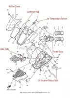
Remove the wiring harness plugs from the 3 Electronic Sensors on the backside of AIR BOX and also remove 3 vacuum hoses, 2 on the bottom of Electronic Sensors and 1 on back of the AIR BOX . Remove the AIR BOX COVER #33 DIAGRAM 4 along with the BAND #3 DIAGRAM 6 that holds the front of AIR BOX to the frame. Remove the 3 GROMMET PLUGS #36 DIAGRAM 4 on top of the AIR BOX and loosen the 3 Allen Bolts #26 through access holes that loosen from Throttle Body. On the bottom of AIR BOX on right side of sled remove Oil Tank Breather Hose #31 and then whole AIR BOX will then come off.
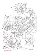
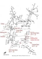
PIVOT ARM DIAGRAM 5 & 6:Remove Steering Arm #43 from Pivot Arm Shaft #42 by removing Circlip #45 and Allen Bolt #44 DIAGRAM 5. Remove Plastic Pivot Arm Cover #10, Dust Boot Covers on left #90, right side #91 of Tie Rods DIAGRAM 6. Remove Clip #72 from Universal Joint on left, right side connected to Idler Arm. Loosen nuts #71 on Universal Joints #67 DIAGRAM 5 to be flush with end of thread do not take completely off. Use a long blunt solid shaft and hammer to shock the Universal Joints loose from Idler Arm about 3-4 hits and Finish removing nuts once broke loose. Remove the 4 bolts #58 DIAGRAM 5 holding the Pivot Arm Assembly to frame and assembly is ready to come out and replace Bushing Kit on workbench. The torque secifications are in the diagrams for reassembly.
Good luck I hope this helps out and why not change the Oil Filter while your in there and any other things that need to be addressed.

Attachments
Similar threads
- Replies
- 6
- Views
- 2K
- Replies
- 116
- Views
- 48K
- Replies
- 46
- Views
- 149K
-
This site uses cookies to help personalise content, tailor your experience and to keep you logged in if you register.
By continuing to use this site, you are consenting to our use of cookies.

